| Home | Online Training | About Us | Syllabus | FAQ | Resources | Components |
Below are some of the components discussed in the online training by Garnett Cross and how to use them in hydraulic systems and ensure trouble free operation.
A special note of appreciation to the individuals and companies who donated these components for cross sectioning.
Check Valves | |
Oil Hydraulics Check Valve cross section. Note: Check valves must be sized according to flow rate and not thread size. | |
Oil Hydraulics Pilot Operated Check Valve cross section. | |
Oil Hydraulics - Hydraulic Fuse Can be used to stop a cylinder falling if a hose bursts | |
Hose Fittings and Couplings | |
Oil Hydraulics Crimp Fitting | |
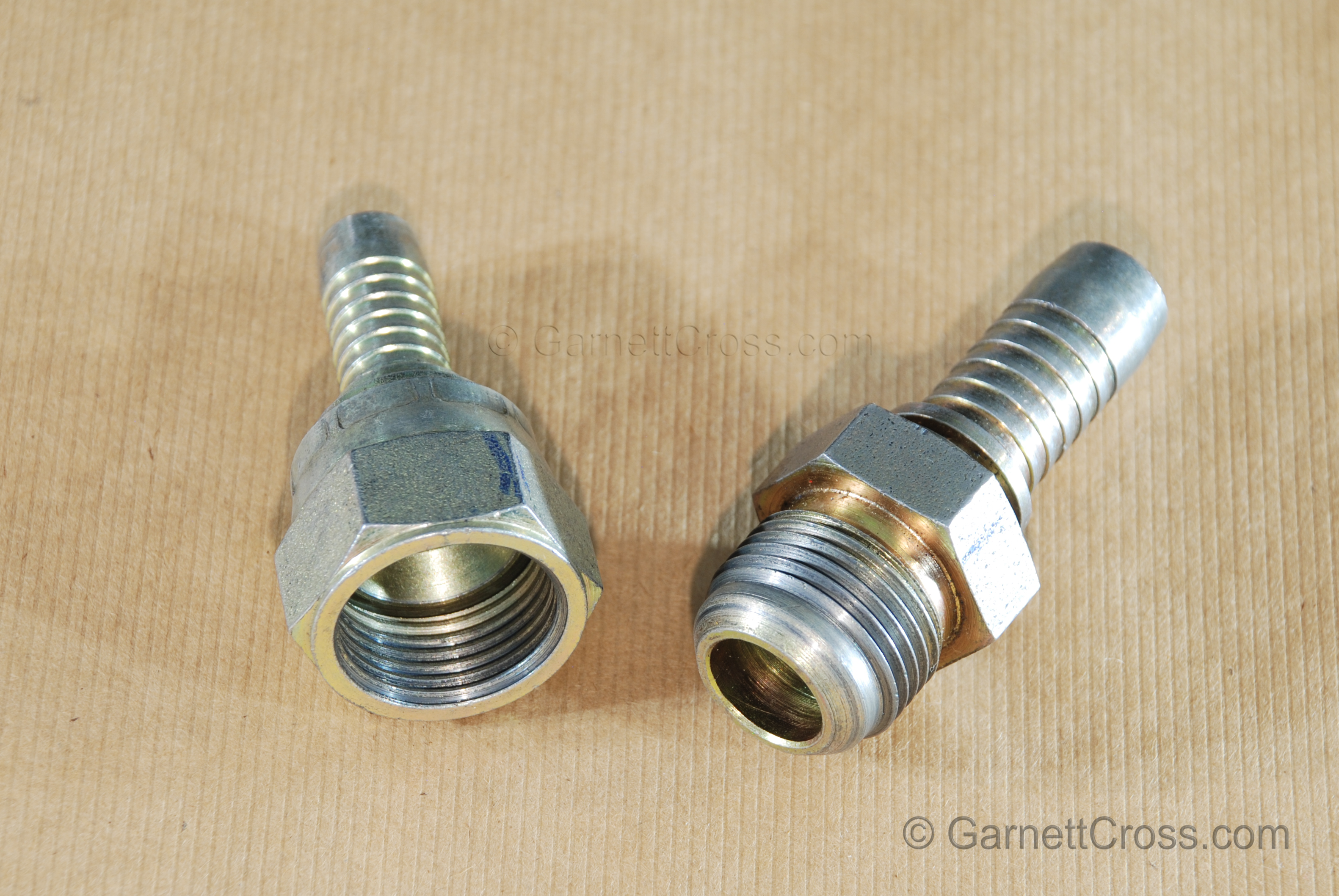
Oil Hydraulics J.I.C fitting (this fitting does not have an o-ring. Note: Follow the J.I.C fitting torquing specification based on the fitting size. | |
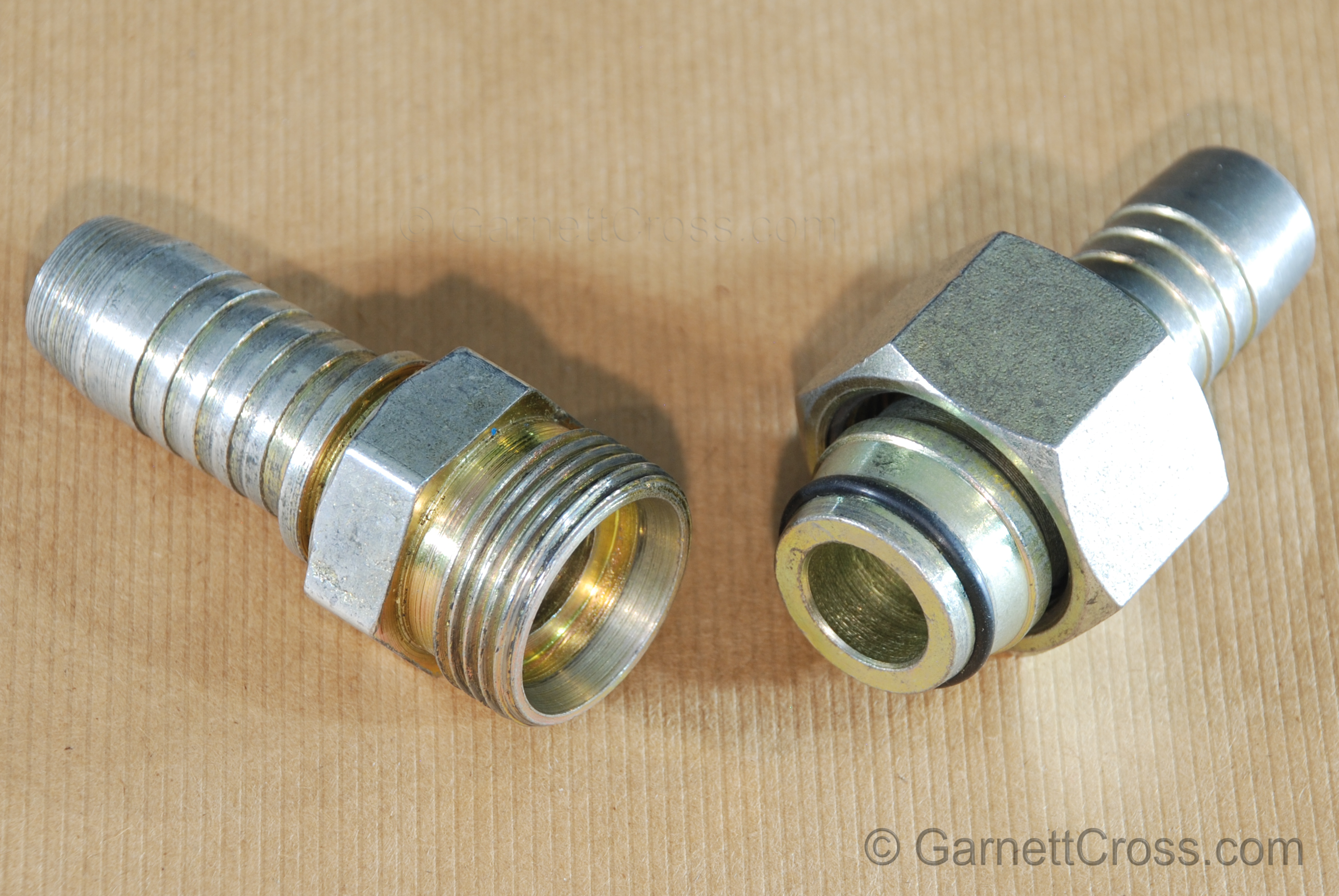
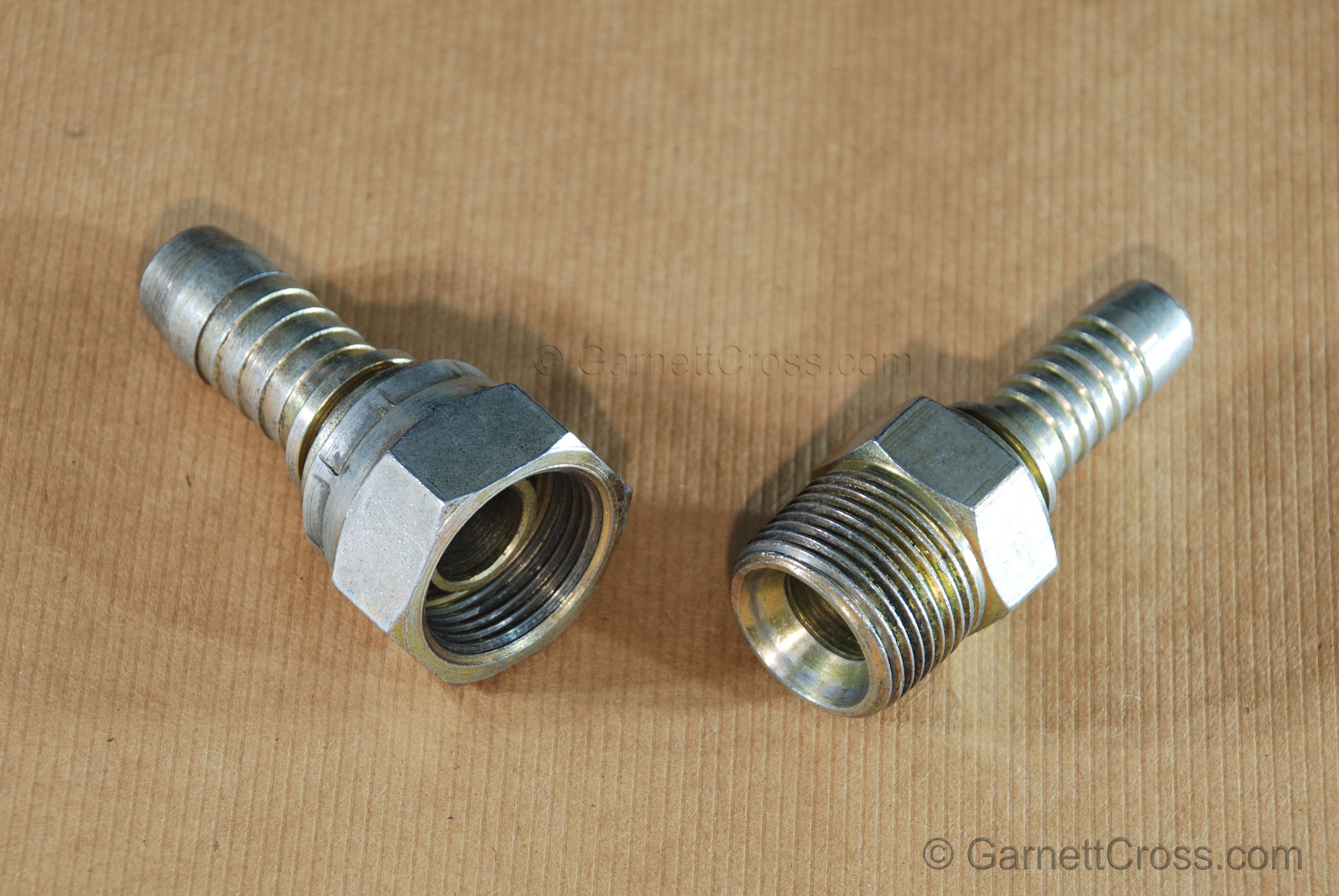
Oil Hydraulics Male/Female taper fitting with o-ring. | |
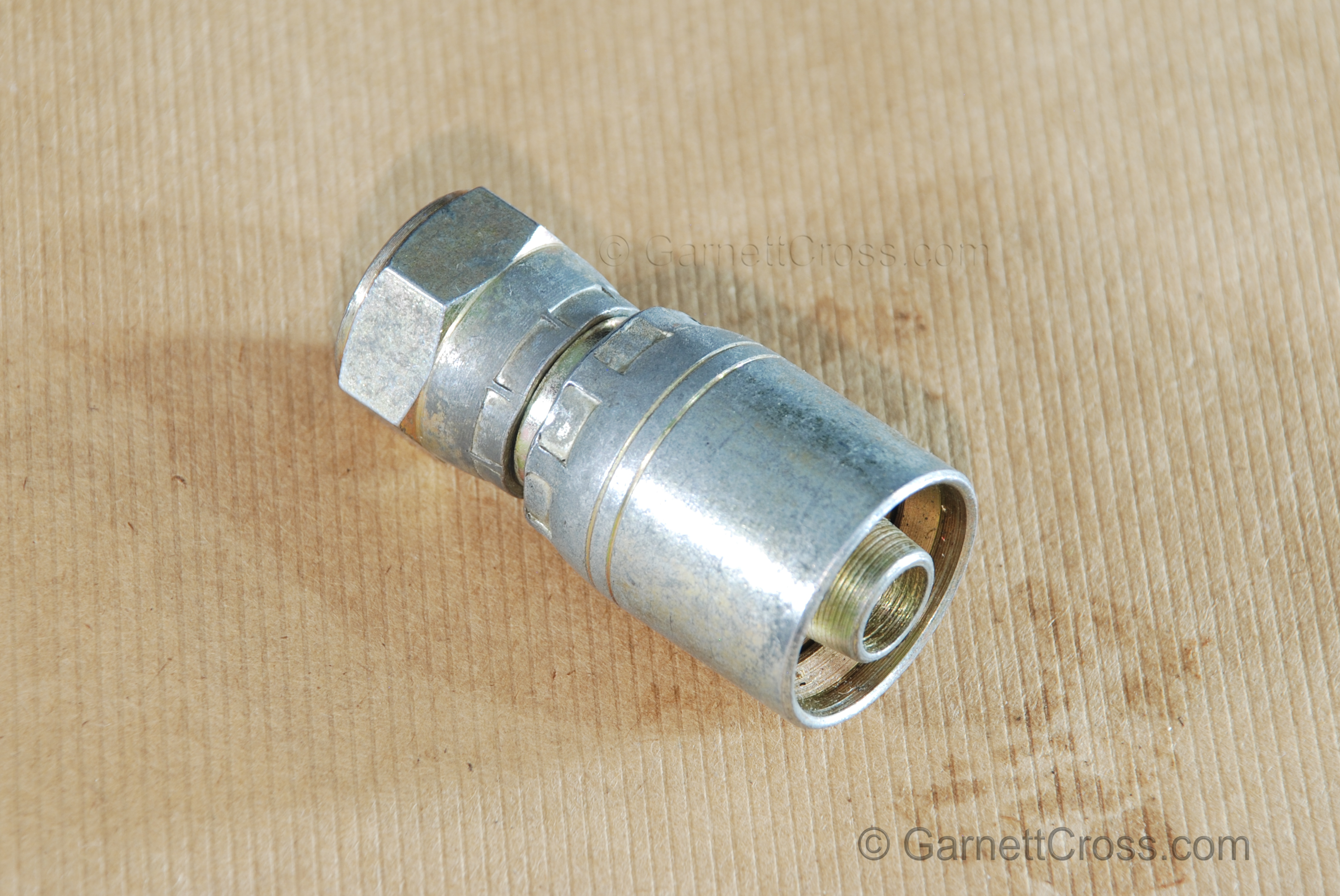
Oil Hydraulics Pre-assembled Swaged Fitting. | |
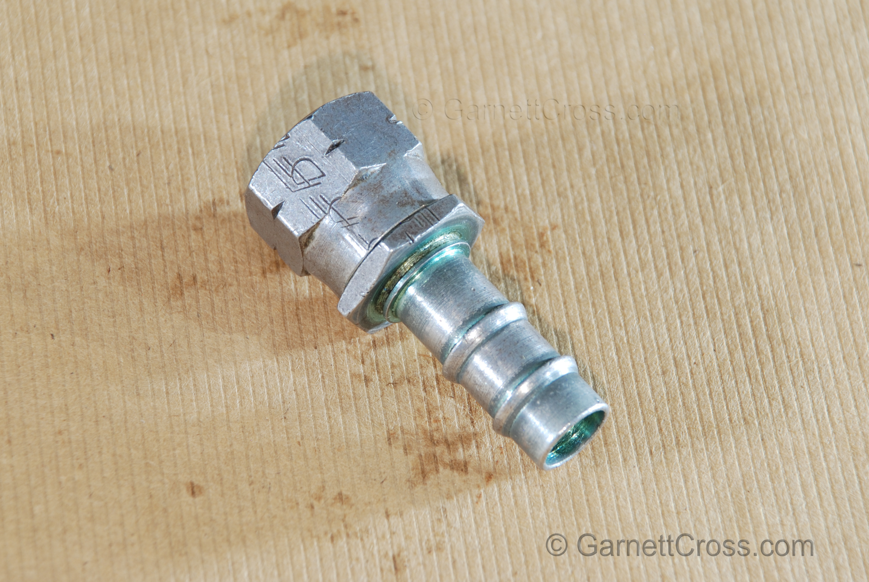
Oil Hydraulics Push Lock fitting. | |
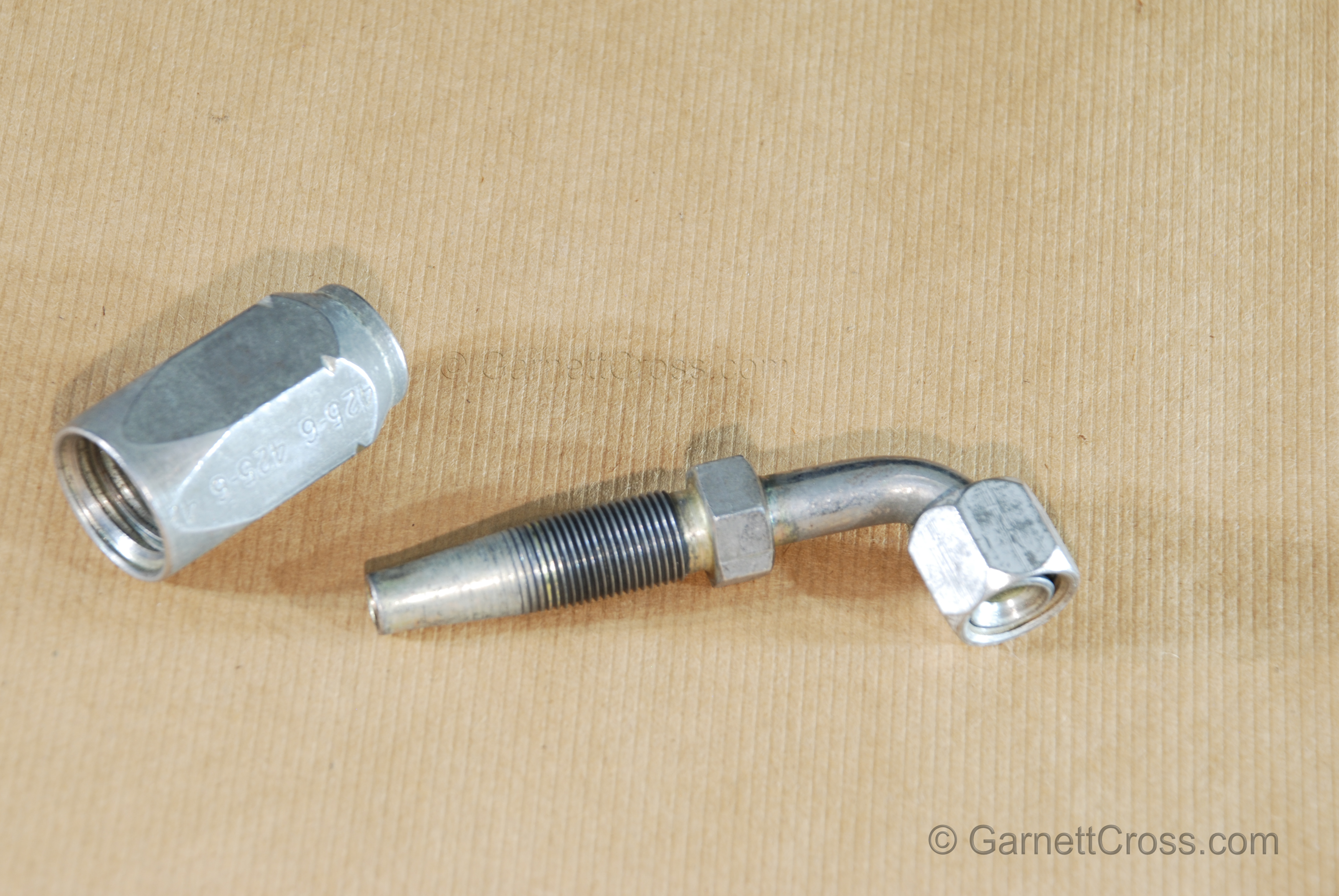
Oil Hydraulics Rubber Hose Field Attachable Fitting (Reusable fitting) No-Skive and Skived, assembled with oil, external part is left-hand threaded, insert is right-hand threaded. | |
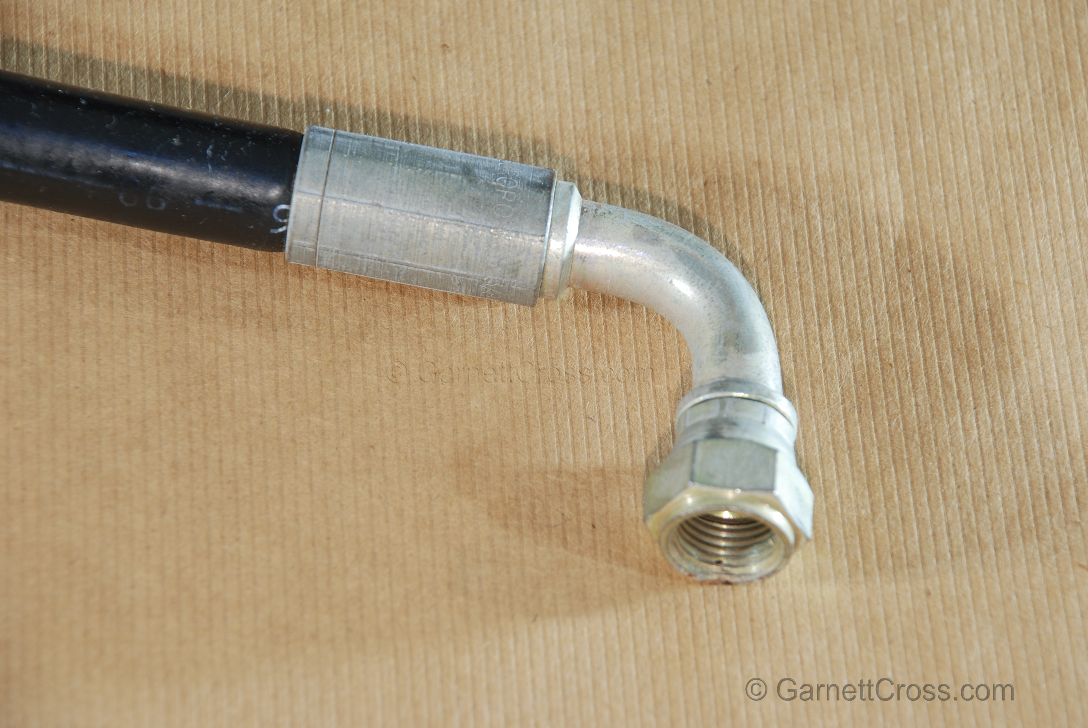
Oil Hydraulics Rubber Hose with 90 degree crimp fitting. | |
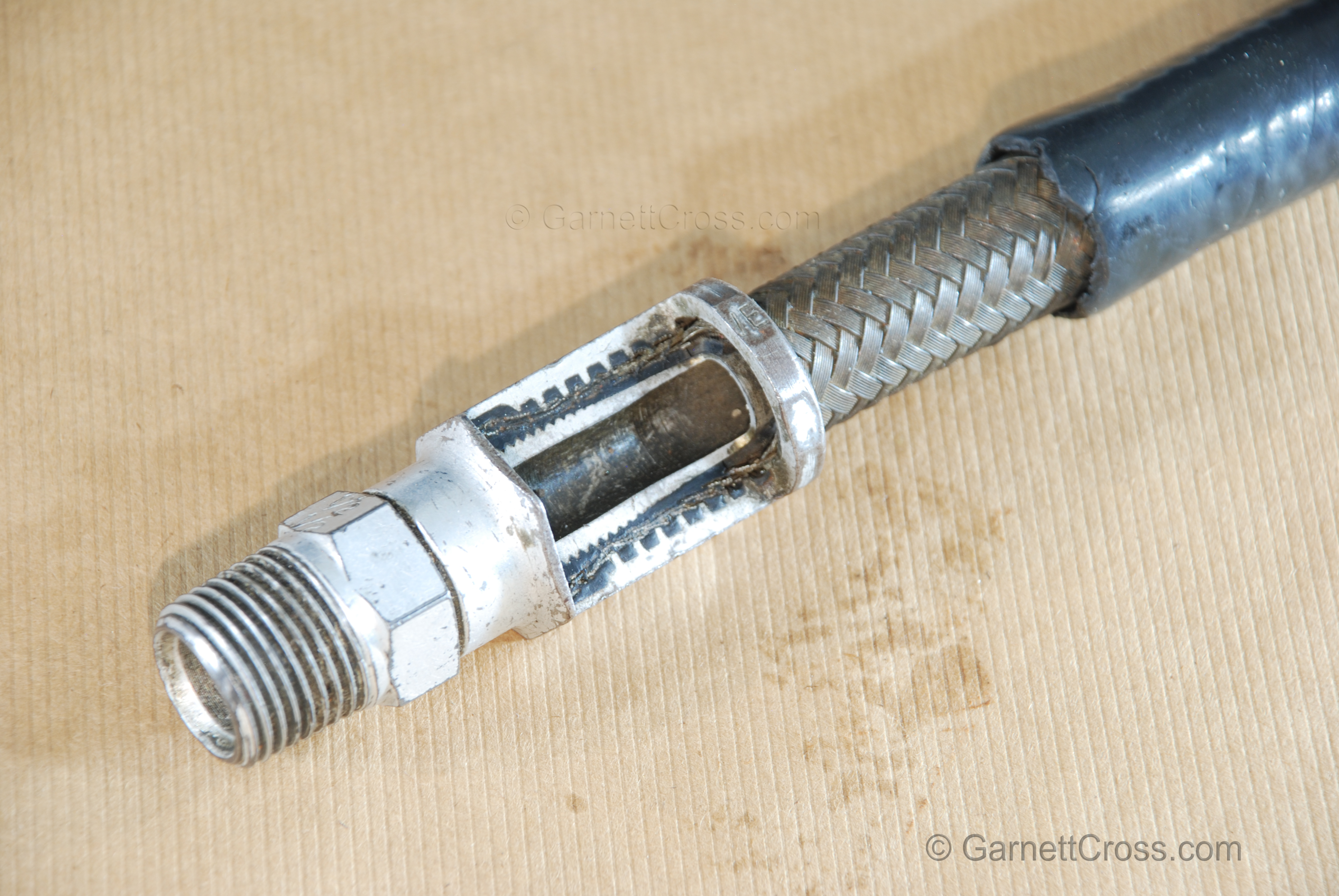
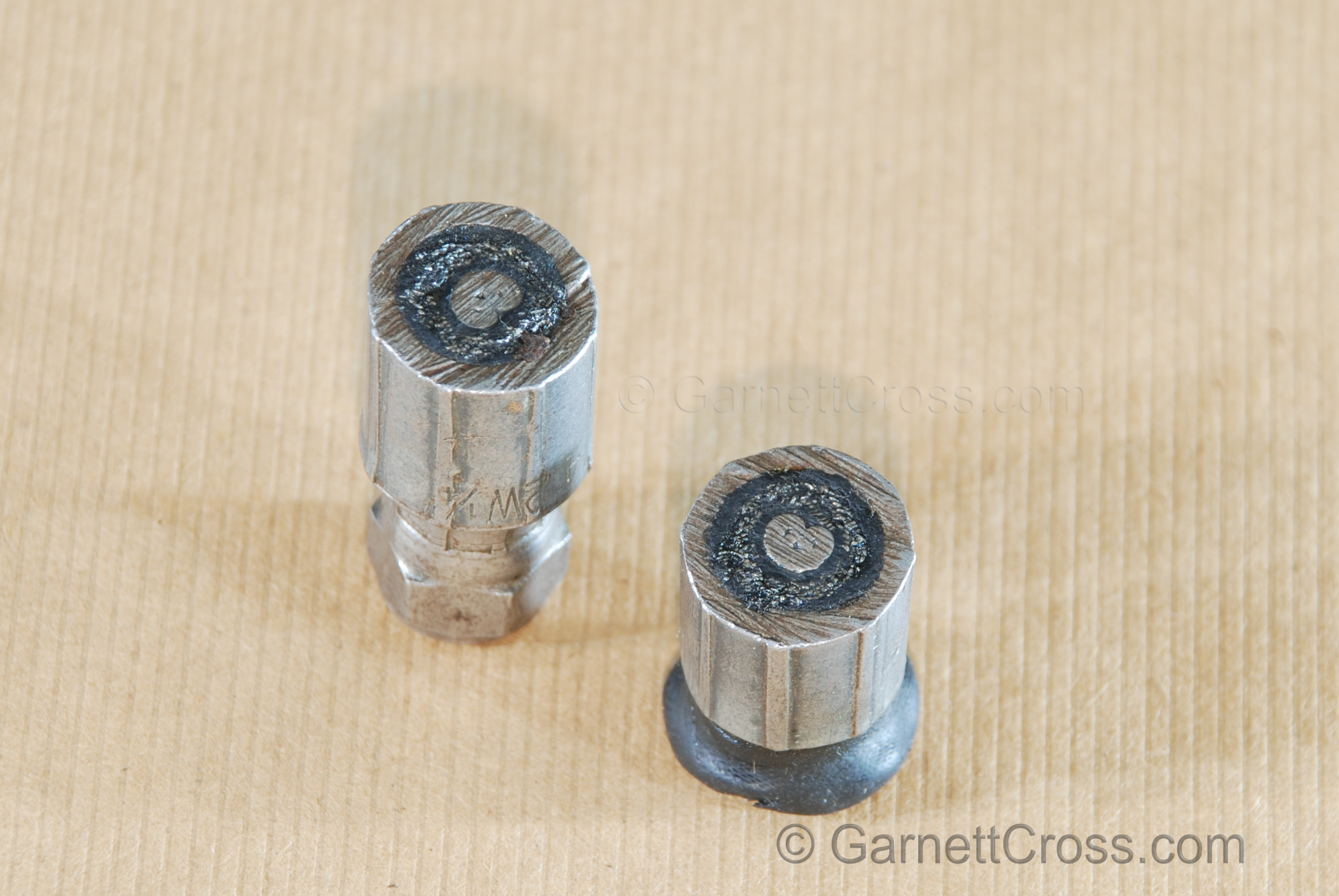
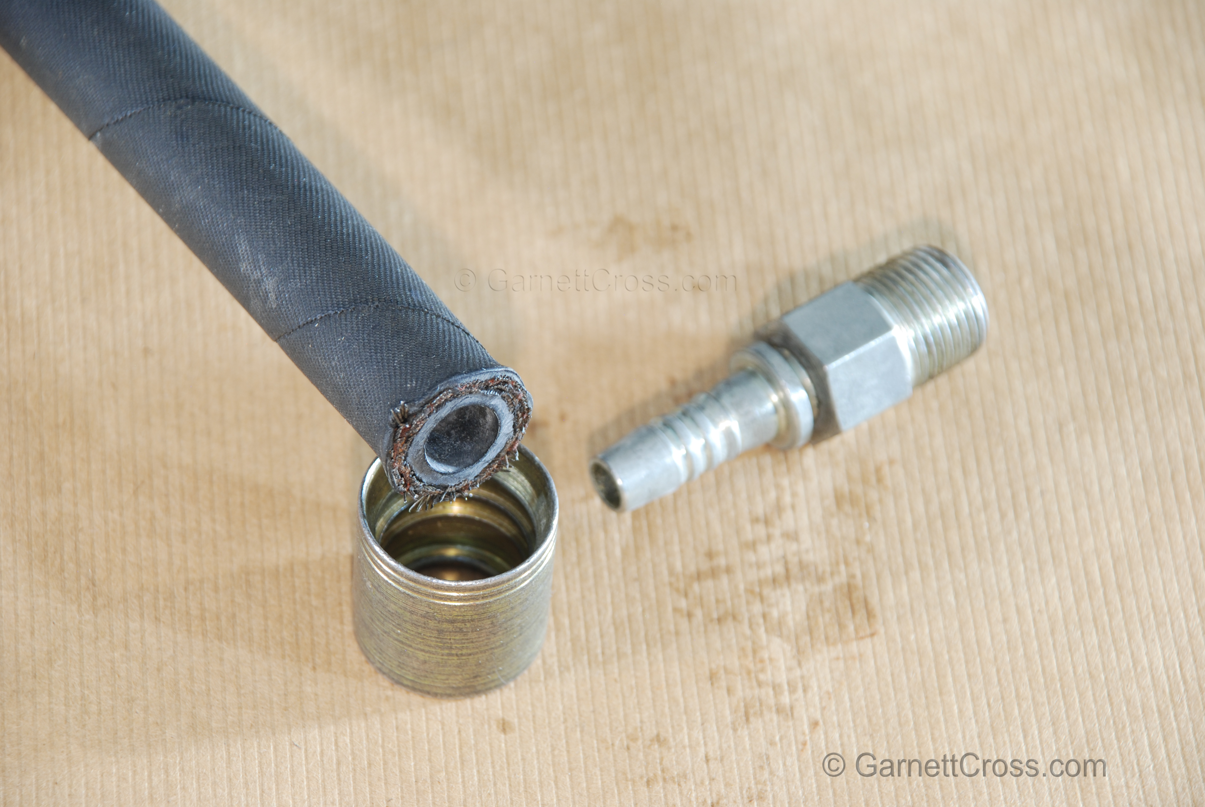
Oil Hydraulics Rubber Hose with Field Attachable Fitting cross-section Note: Hose diameters are measured in the bore, but the R5 hoses the outer diameter of the inner tube is measured as the hose diameter. All hoses must be supplied with fittings cleaned and capped, numbered and supplied with a test certificate stating the hose was tested to twice the hose working pressure. This is to test the integrity between the hose and the fitting. (Note: the burst pressure of a hose is 4 times the working pressure) | |
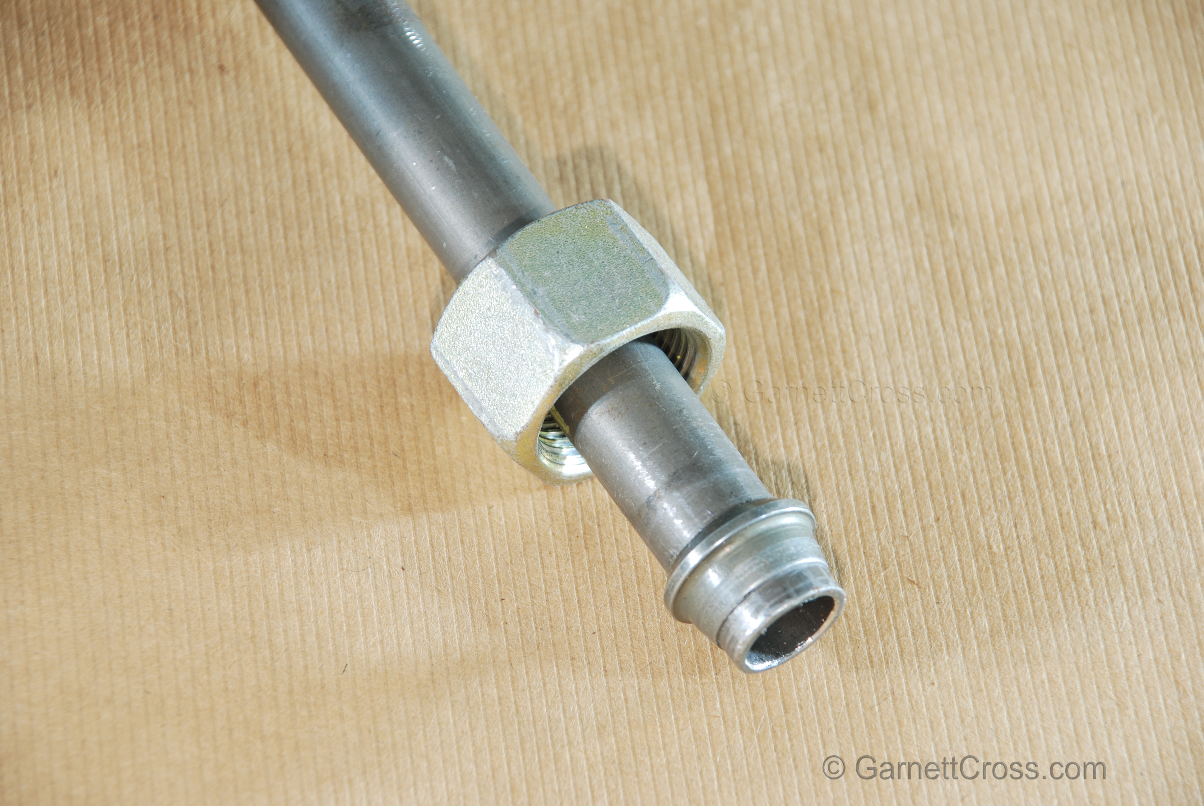
Oil Hydraulics Steel Tube with Ferrule Compression Fitting | |
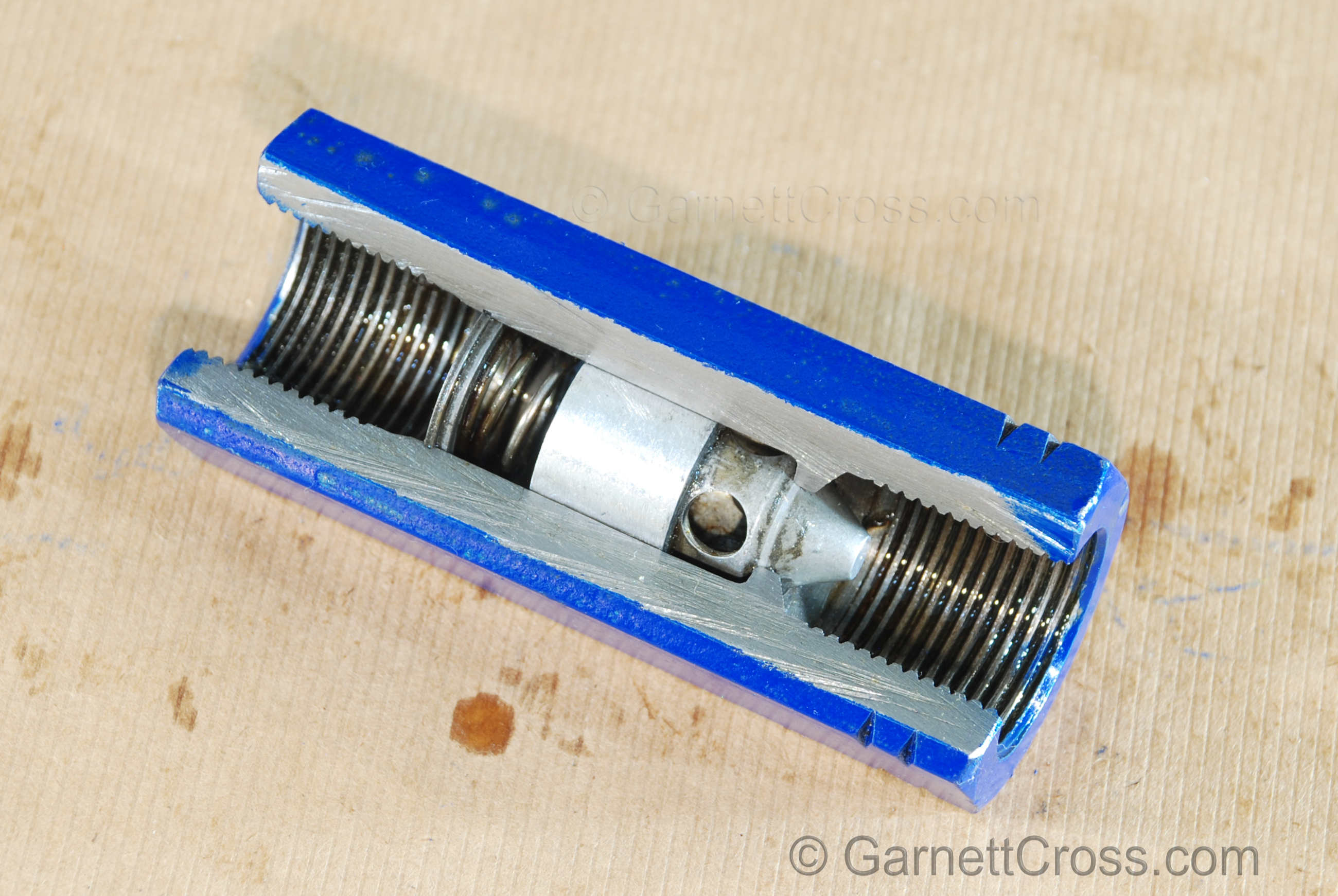
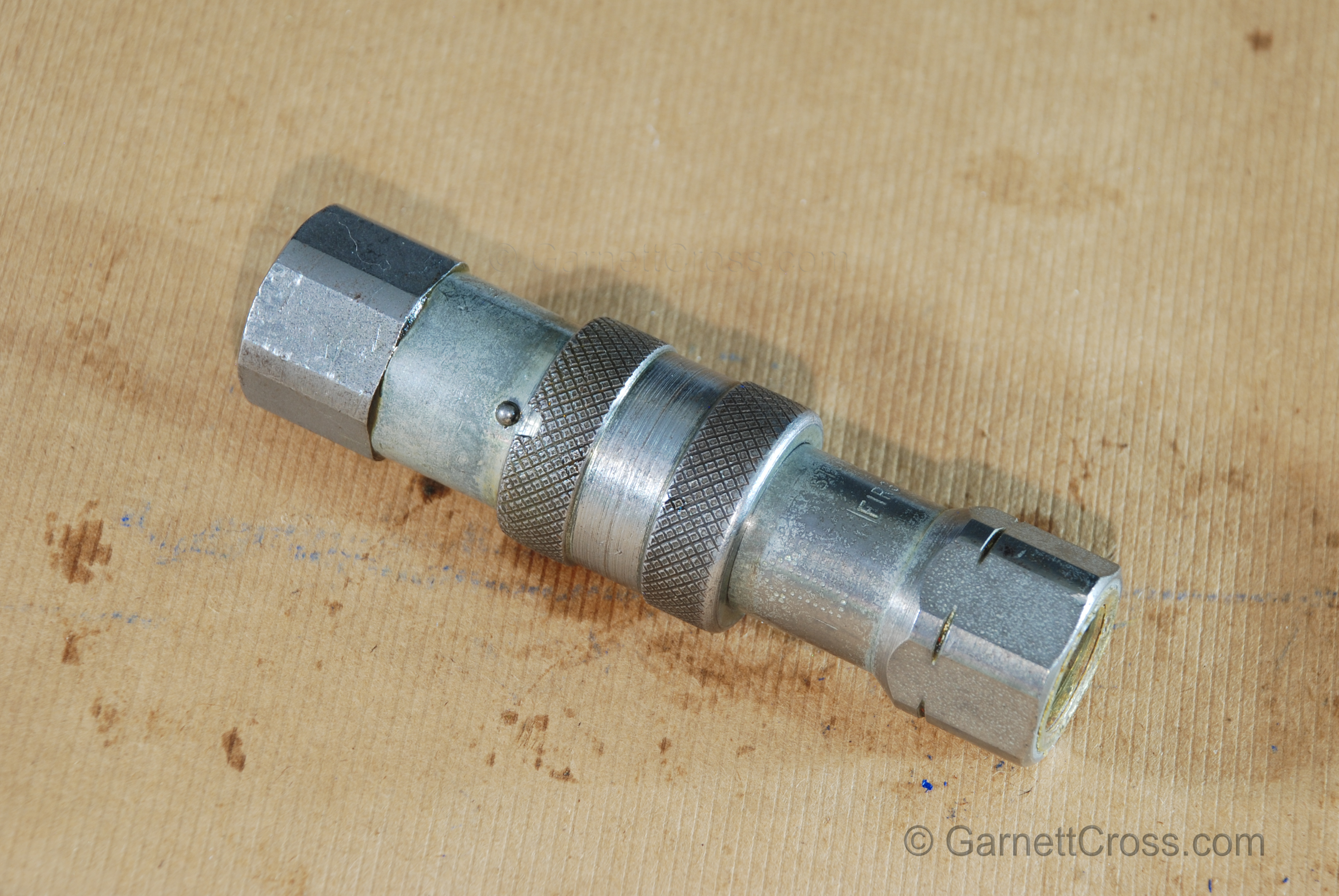
Oil Hydraulics Threaded Flat-End Quick Coupling connected Note: The ball is aligned with the slot in the sleeve for uncoupling. | |
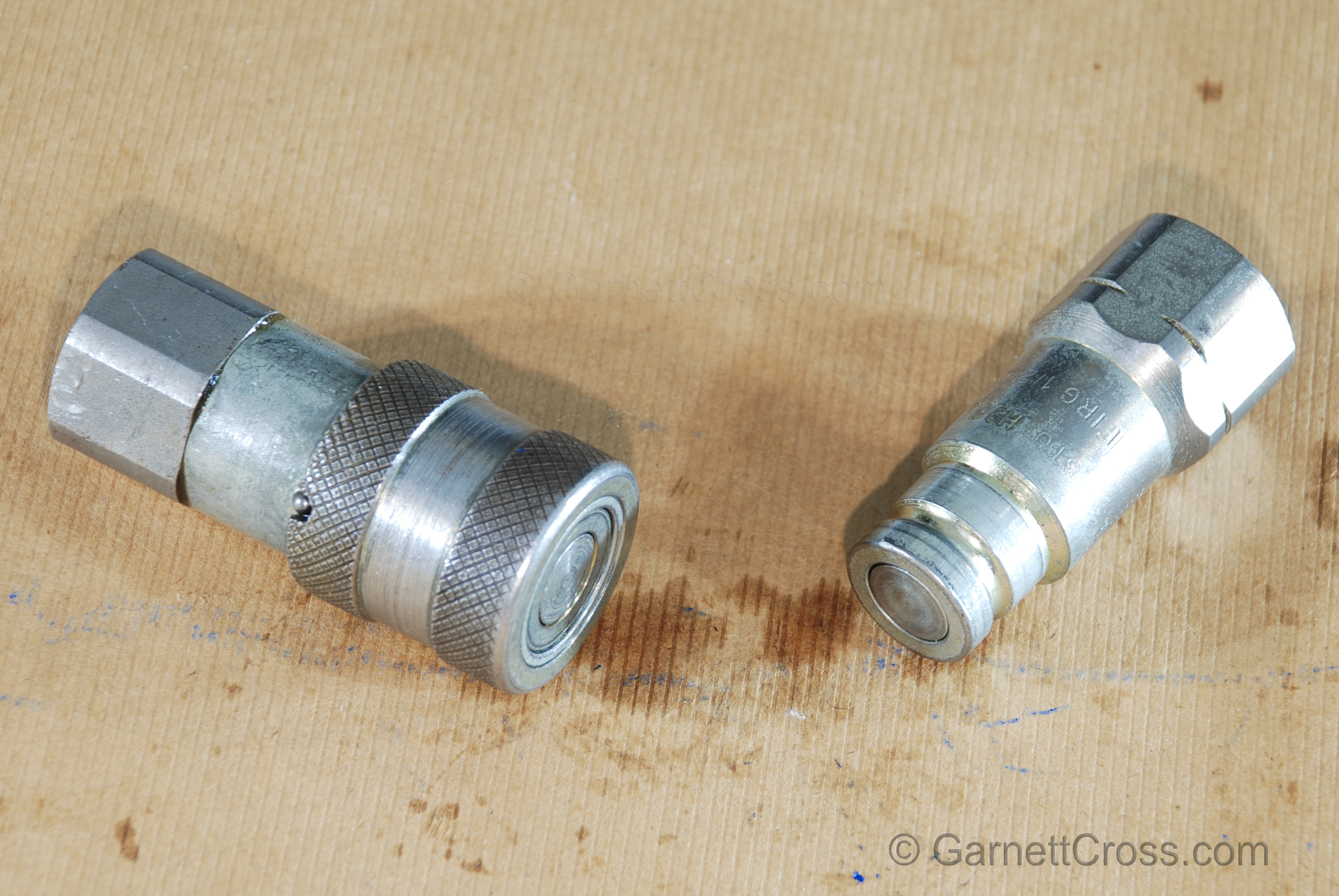
Oil Hydraulics Threaded Flat-End Quick Coupling separated Note: Always size couplings by the flow-rate that has to pass through them and never by the thread size. The slot in the outer sleeve is aligned with the ball for uncoupling. | |
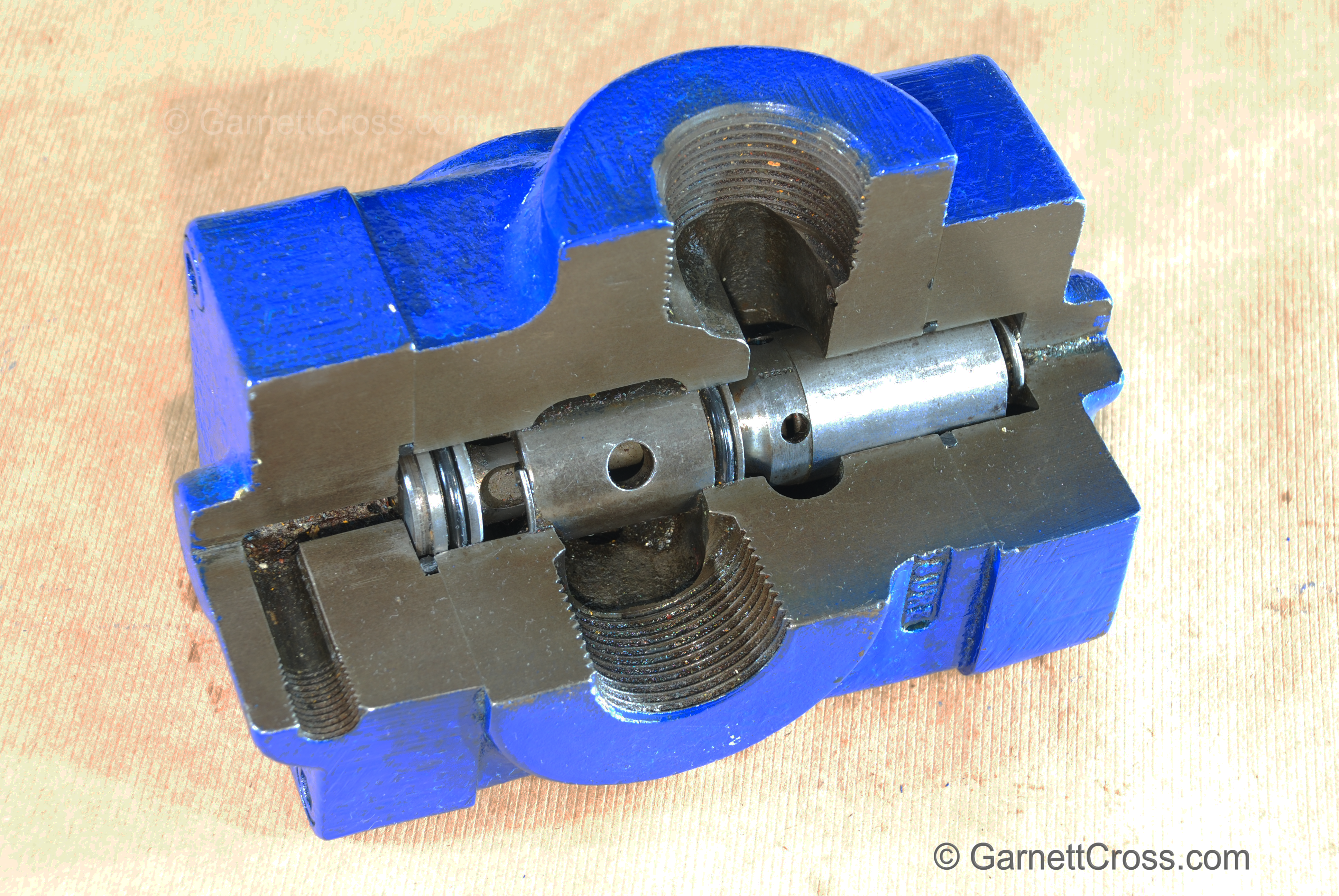
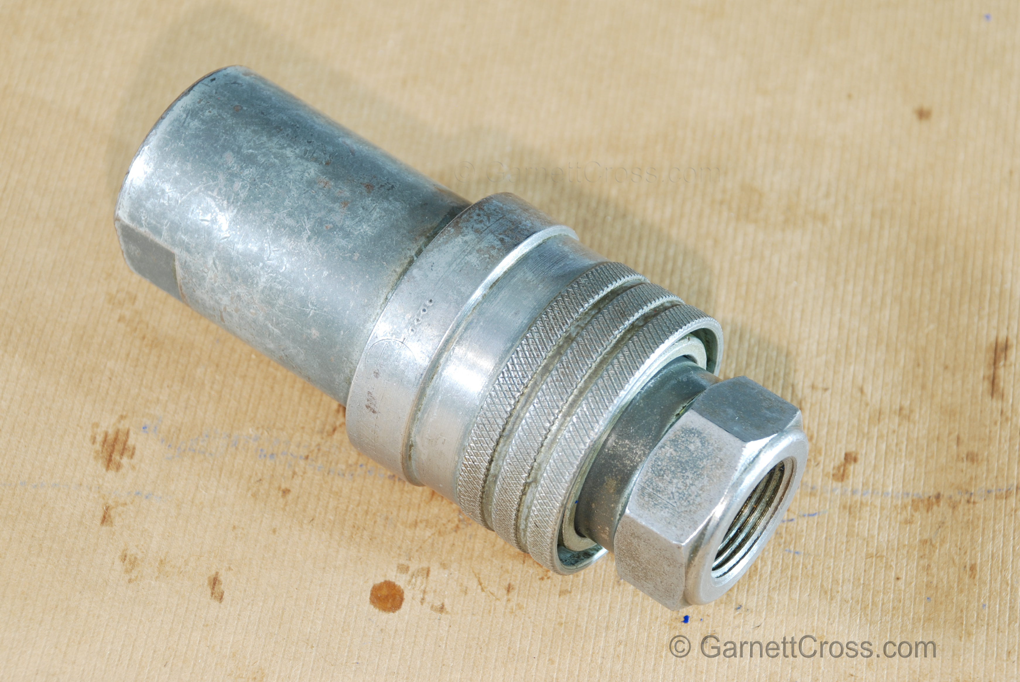
Oil Hydraulics Threaded Quick Coupling connected | |
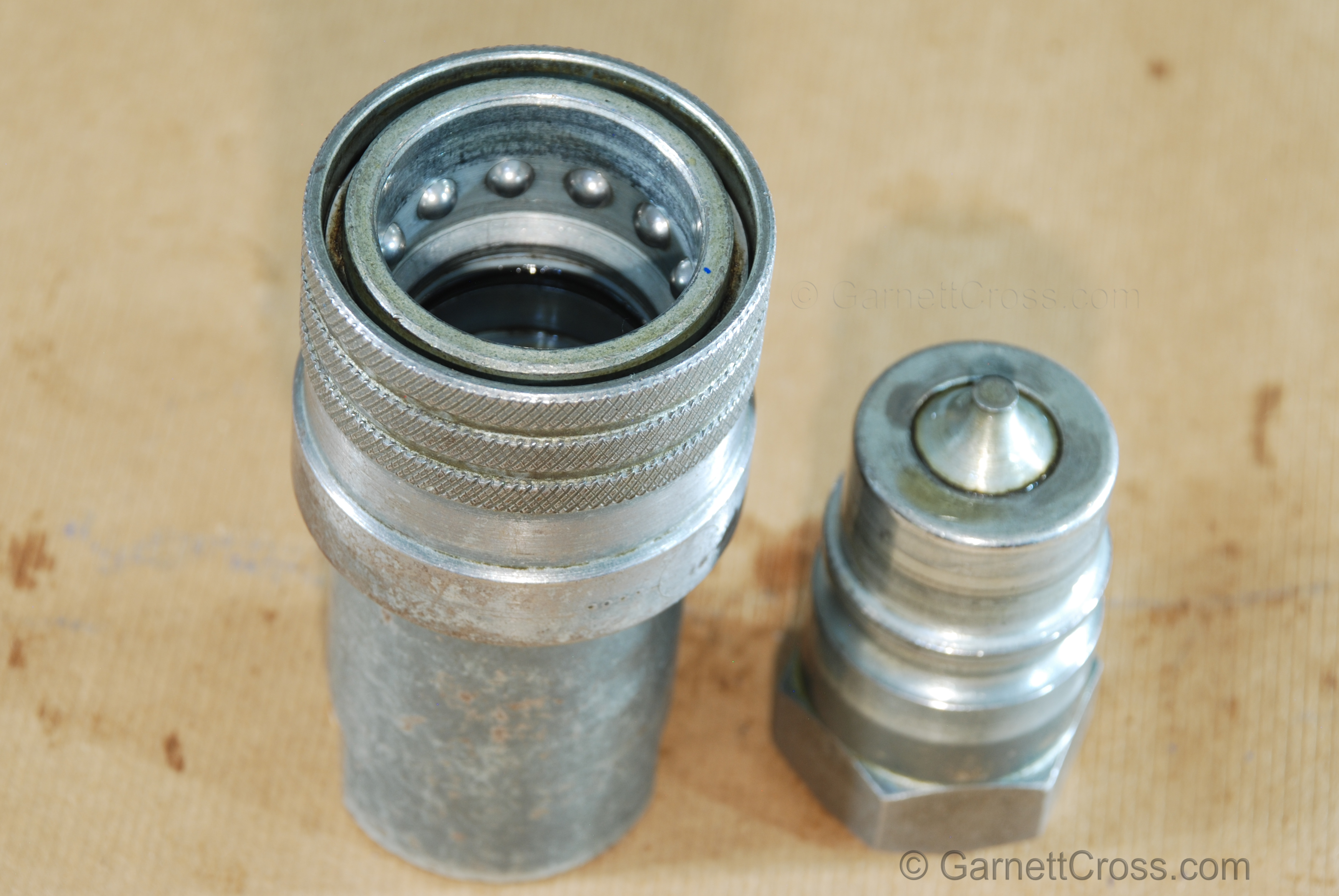
Oil Hydraulics Threaded Quick Coupling separated | |
Oil Hydraulics Threaded Quick Coupling separated | |
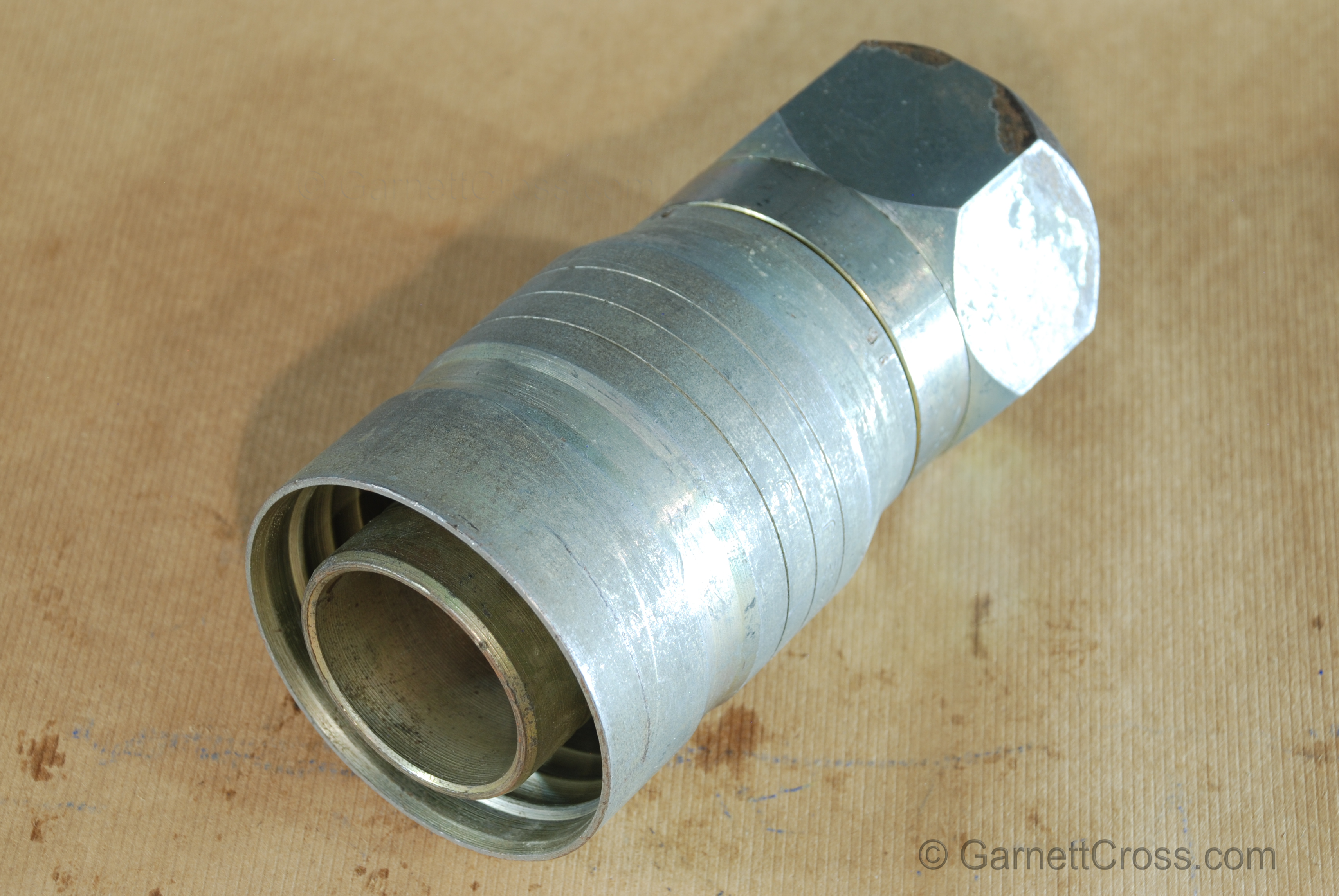
Oil Hydraulics bullnose fitting (this coupling does not have an o-ring). | |
Oil Hydraulics example of swaged fitting that had been over crimped collapsing the insert. Note: This caused unnecessary time loss to the plant trying to determine the cause of zero flow. | |
Directional Control Valves | |
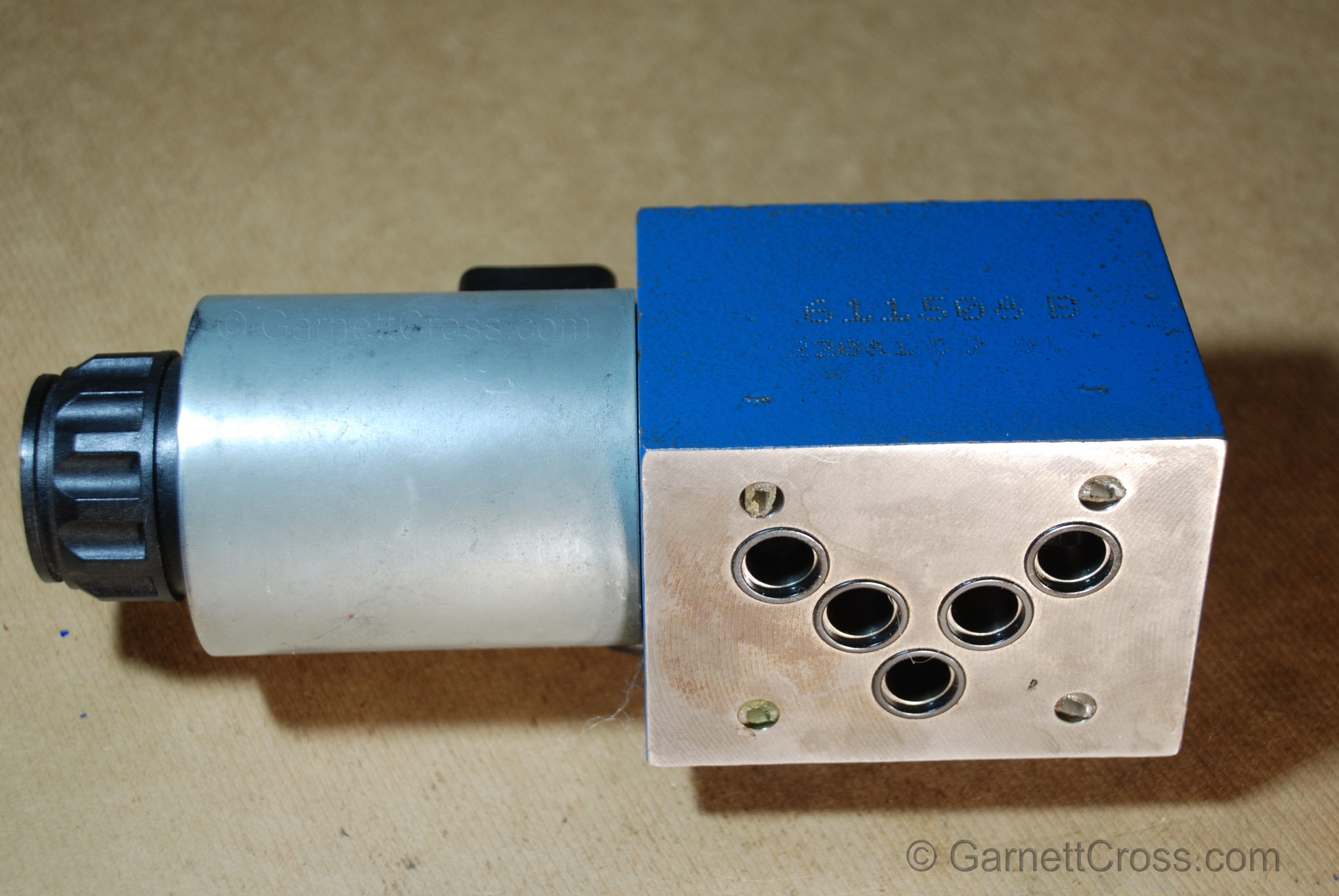
Oil Hydraulics NG10 (CTOP 5) Solenoid Controlled Valve mounting surface. Note: The solenoids are easily replaceable. Always ensure the correct voltage is used for the solenoid. | |
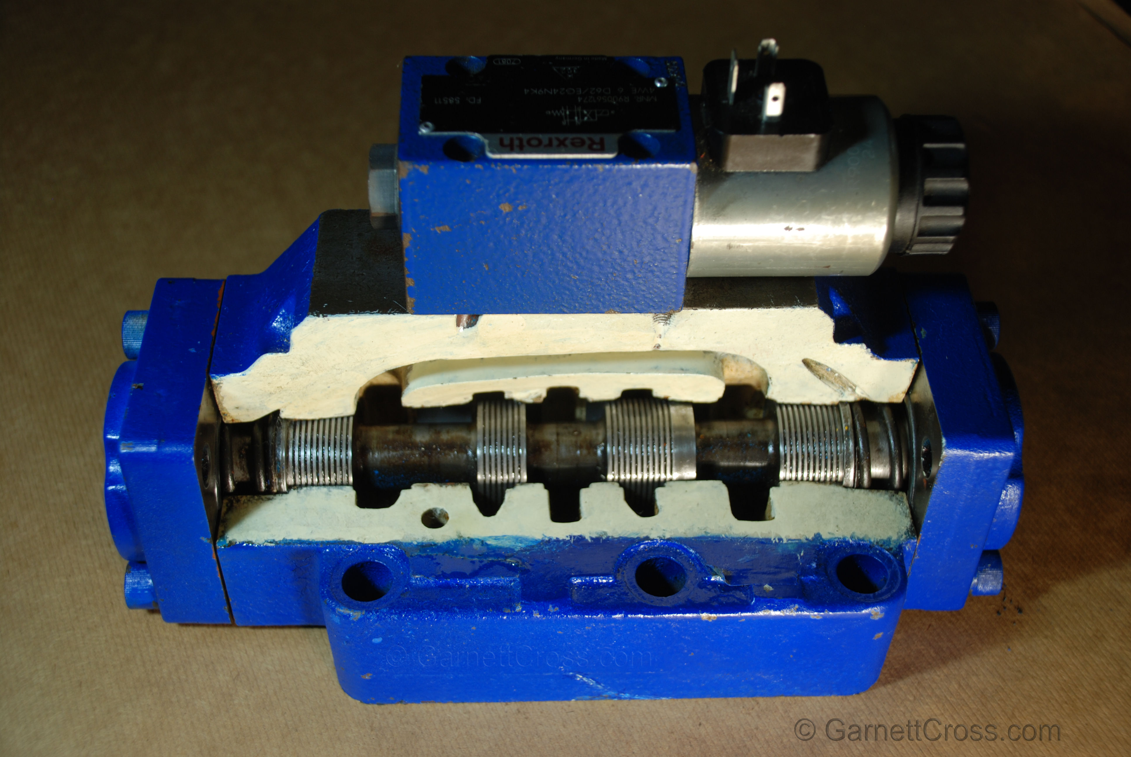
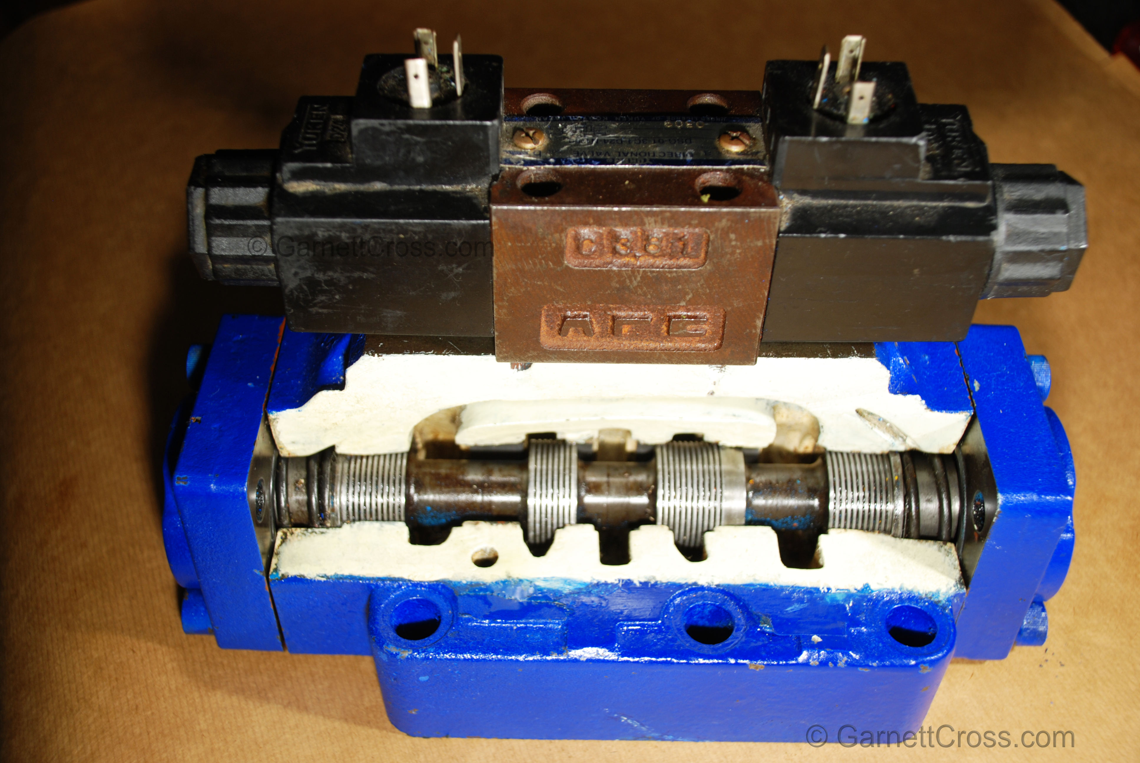
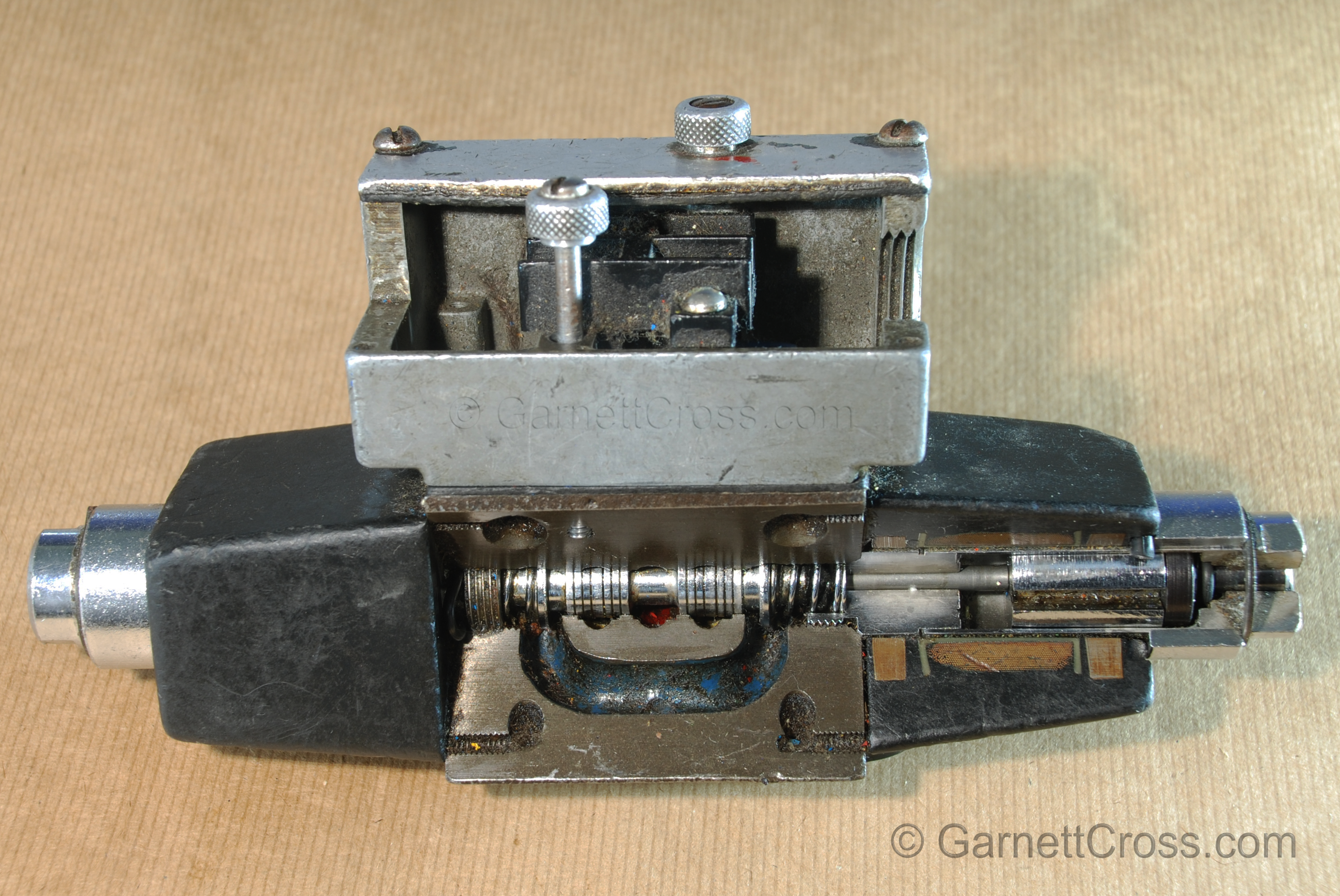
Oil Hydraulics NG25 Pilot Operated Directional Control Valve cross section and Single Acting NG6 (CTOP 3) Solenoid Valve mounted on top. | |
Oil Hydraulics NG25 Pilot Operated Directional Control Valve cross section and double acting NG6 (CTOP 3) Solenoid Valve mounted on top Note: the pitch of the mounting holes are 40.5 millimeters apart and at 90 degrees the mounting holes are 31mm and 32.5mm apart, it can only be mounted one way irrespective of the name tag. | |
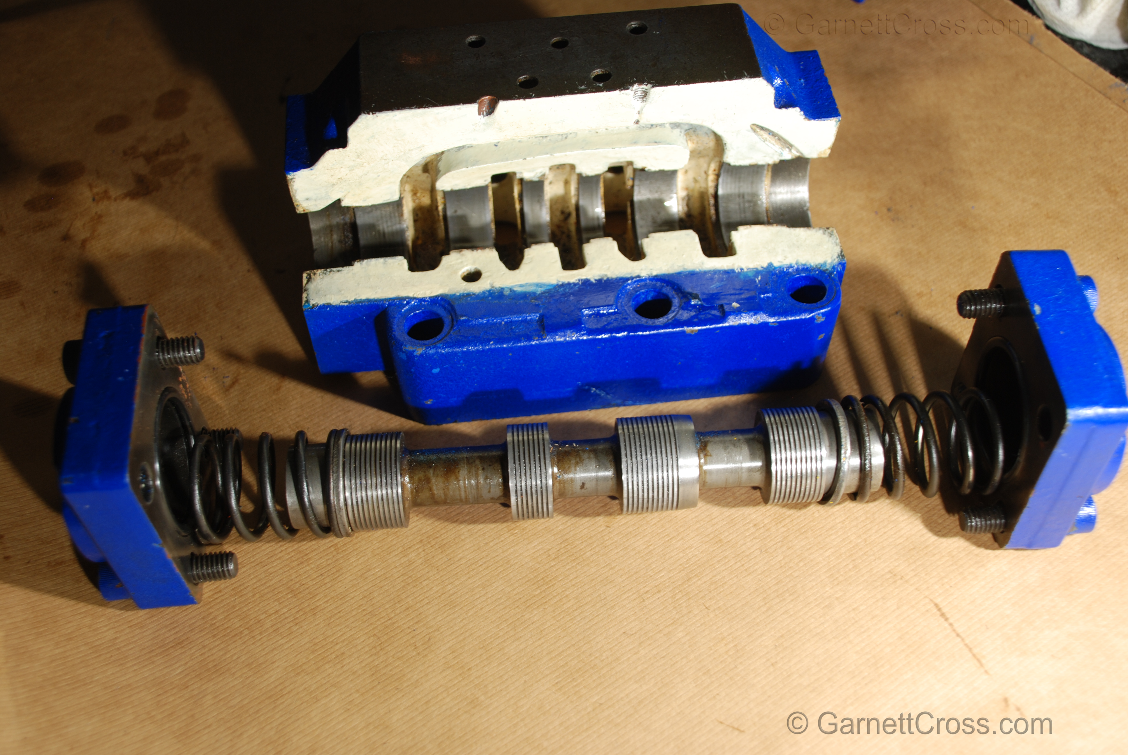
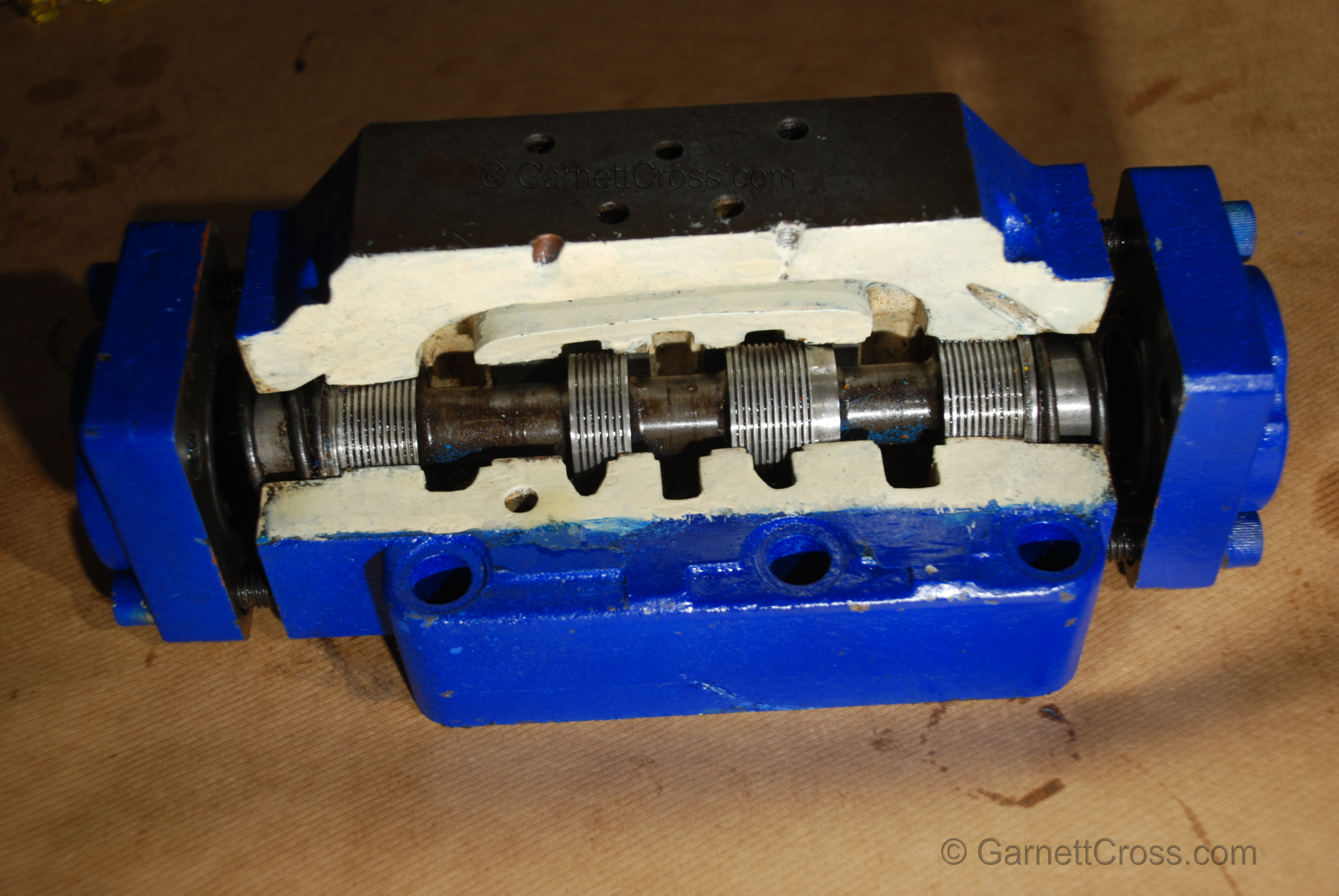
Oil Hydraulics NG25 Pilot Operated Directional Control Valve cross section and spool removed. | |
Oil Hydraulics NG25 Pilot Operated Directional Control Valve cross section partially preassembled. Note: Centering Springs on either end. | |
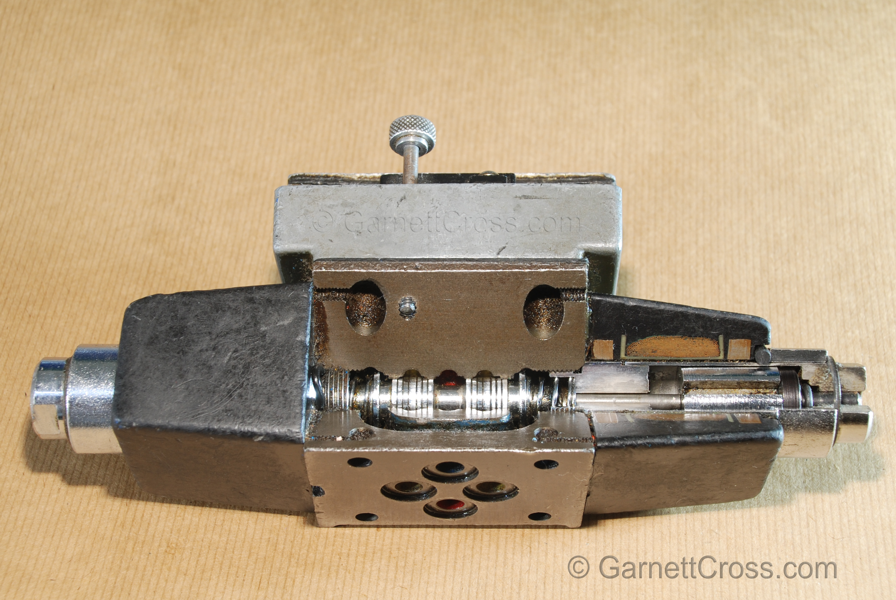
Oil Hydraulics Solenoid Valve NG6 (CTOP 3) Note: Old type valve before the Hirschmann plugs | |
Oil Hydraulics Solenoid Valve NG6 (CTOP 3) Note: Old type valve before the Hirschmann plugs | |
Flow Control Valves | |
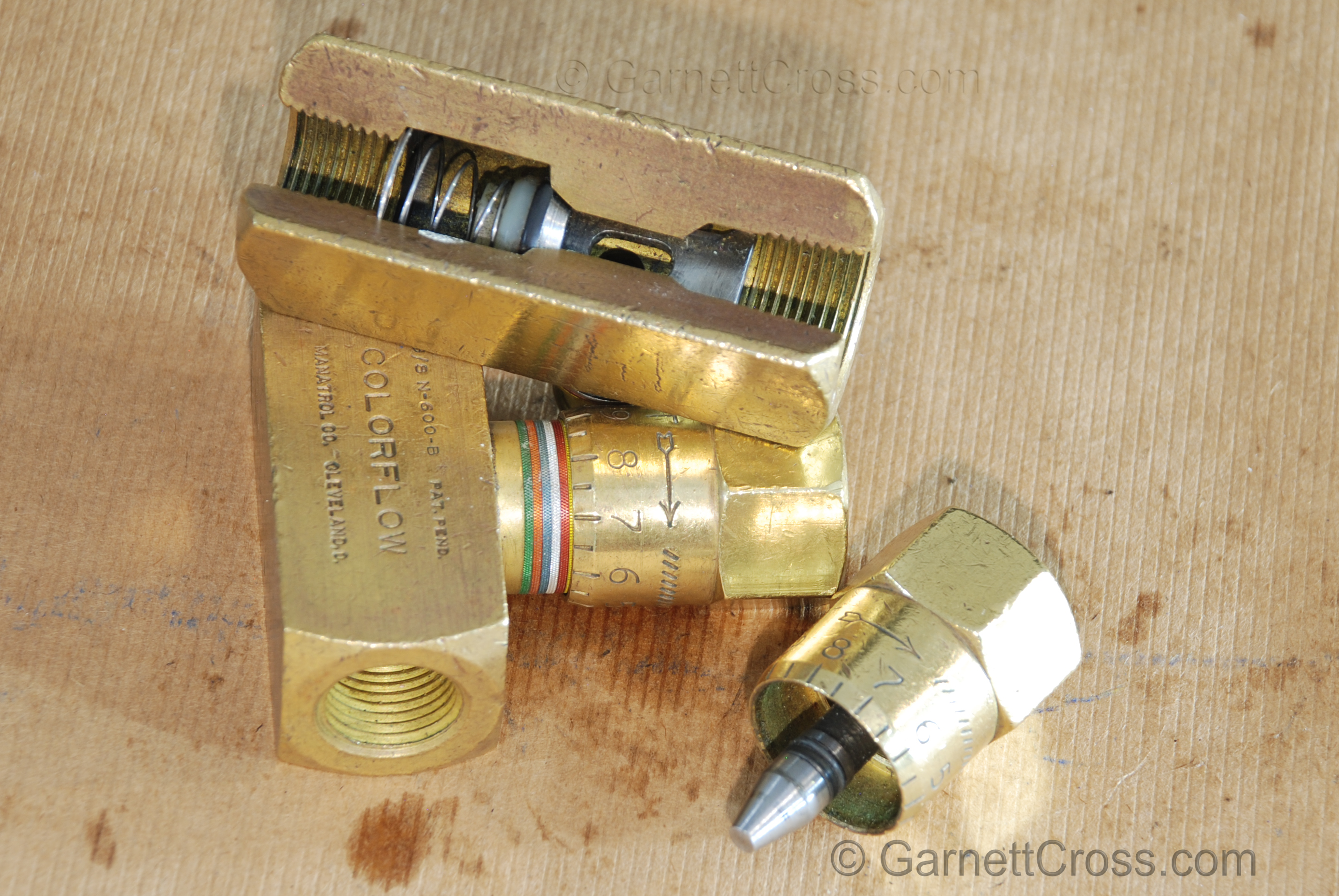
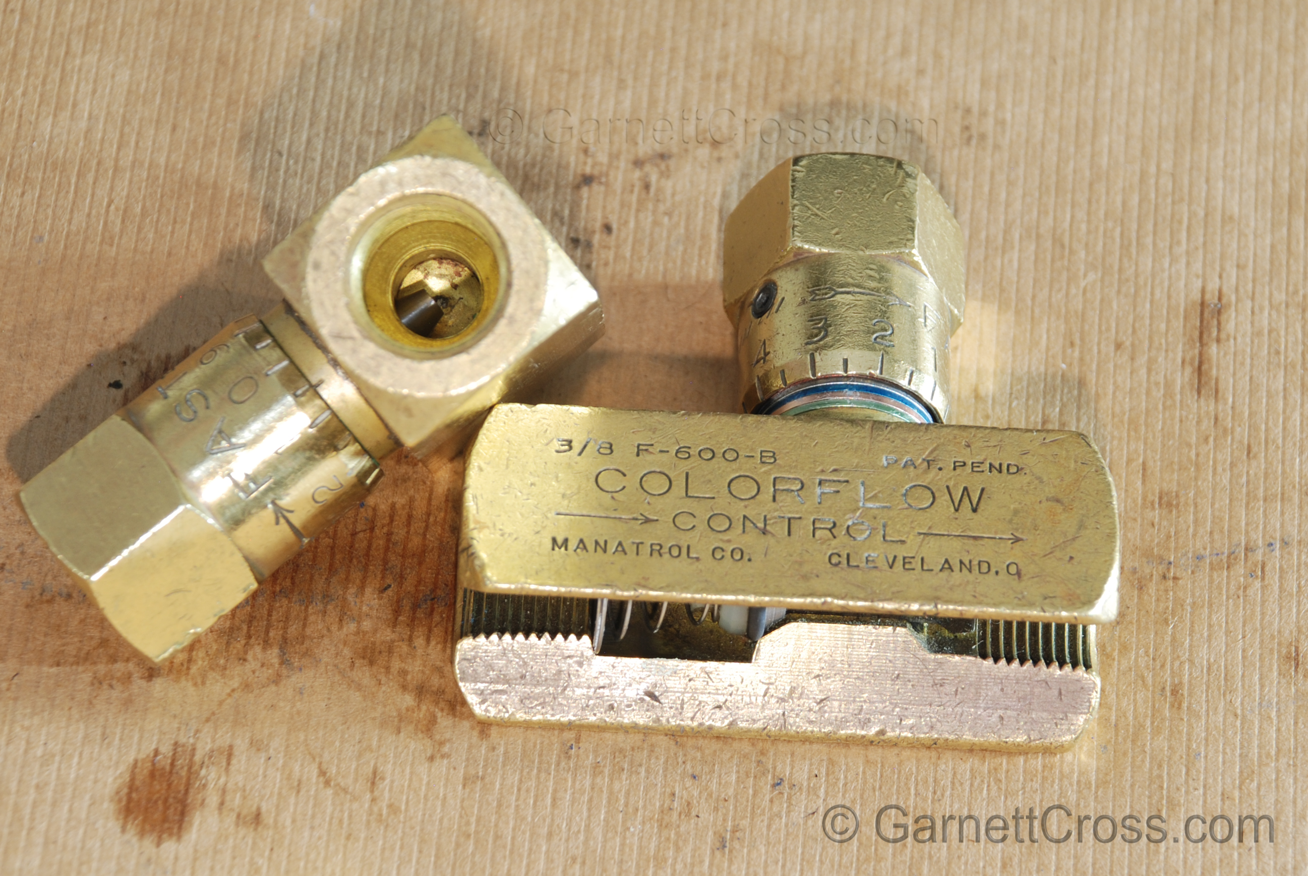
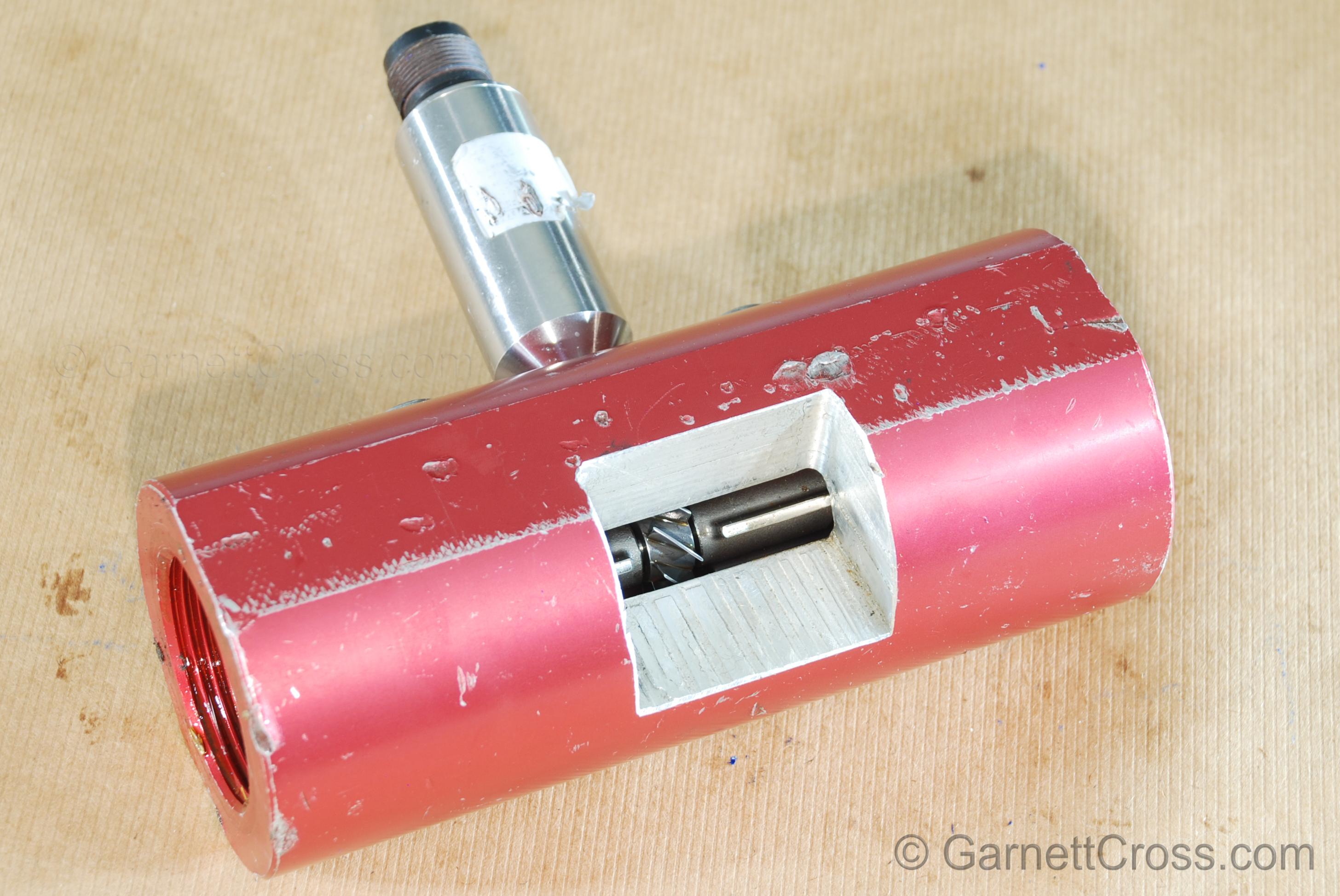
Oil Hydraulics Flow Control Valve with Check Valve cross section with needle lying separately. | |
Oil Hydraulics Flow Control Valve with needle visible. | |
Flow Meters | |
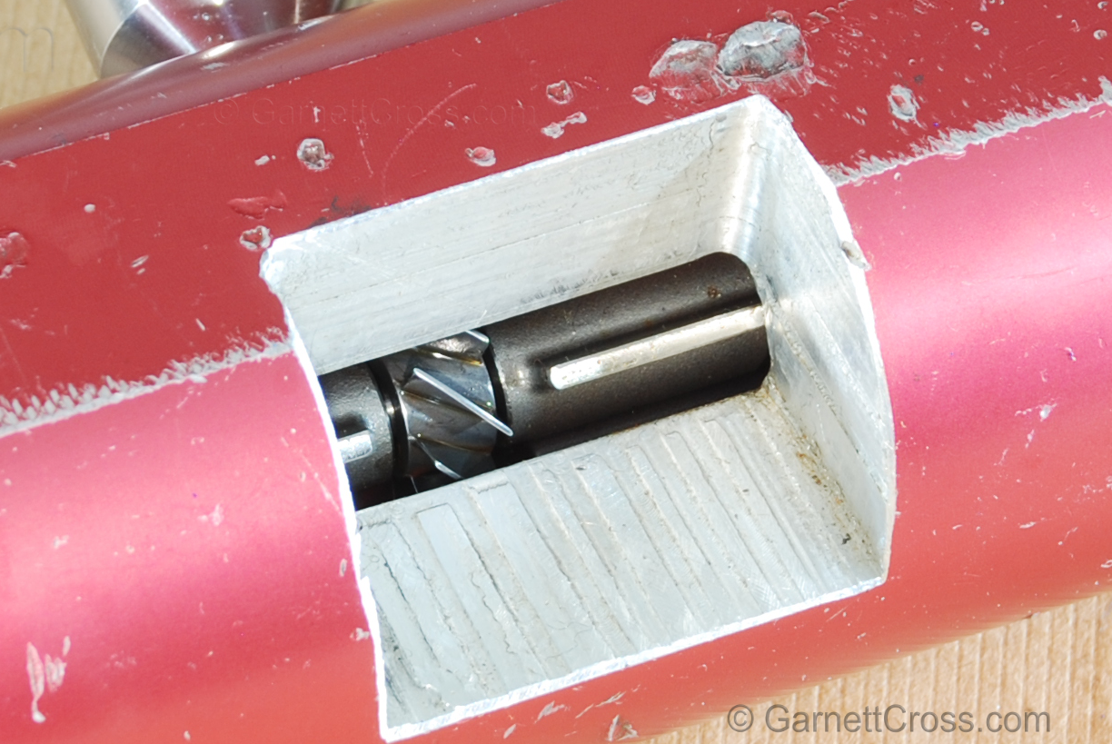
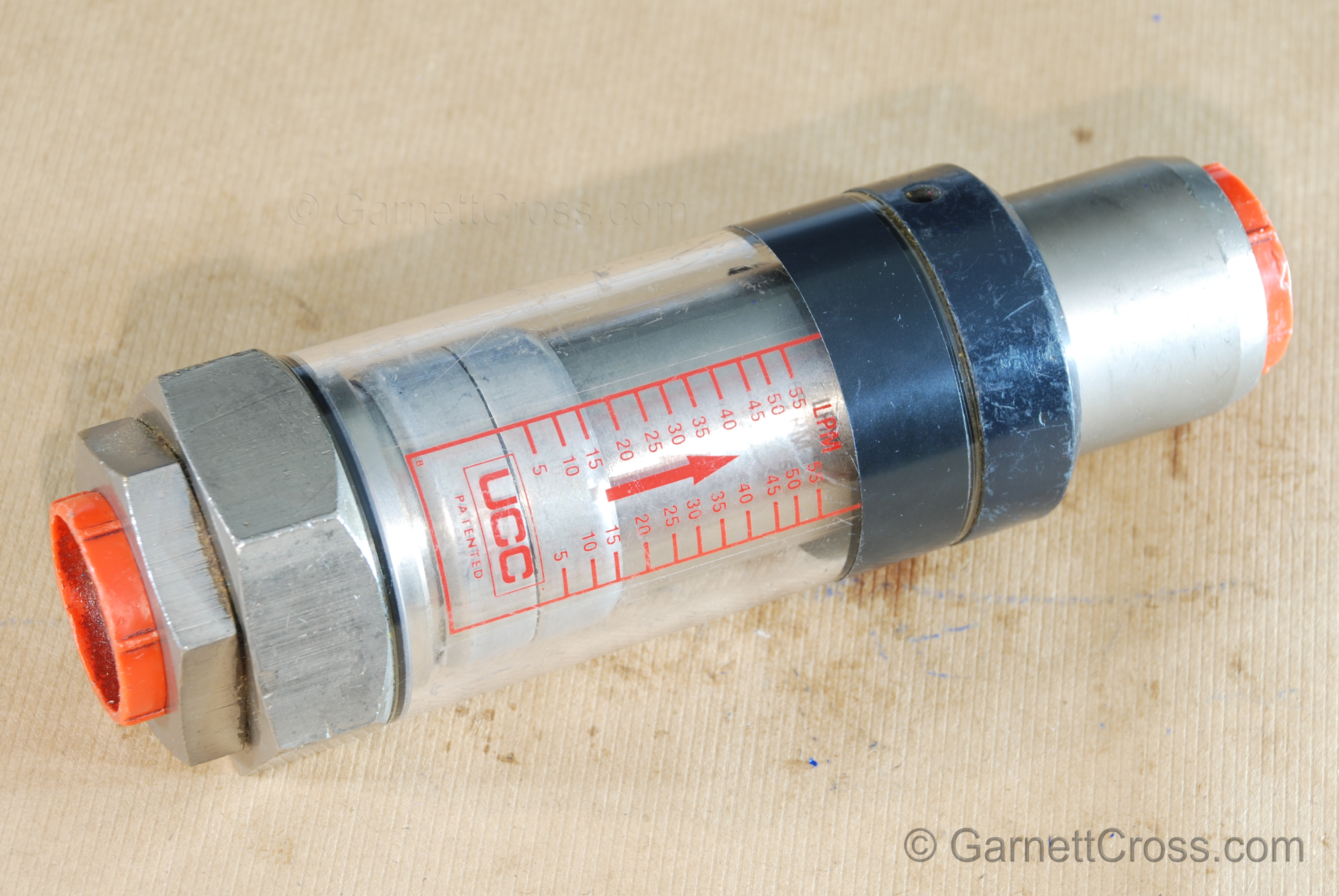
Oil Flow meter cross section - closeup | |
Oil Hydraulics Flow Meter | |
Oil Hydraulics Oil Flow meter cross section. Note: The turbine must be directly opposite the sensor, the position may be adjusted internally. | |
Hydraulic Cylinders | |
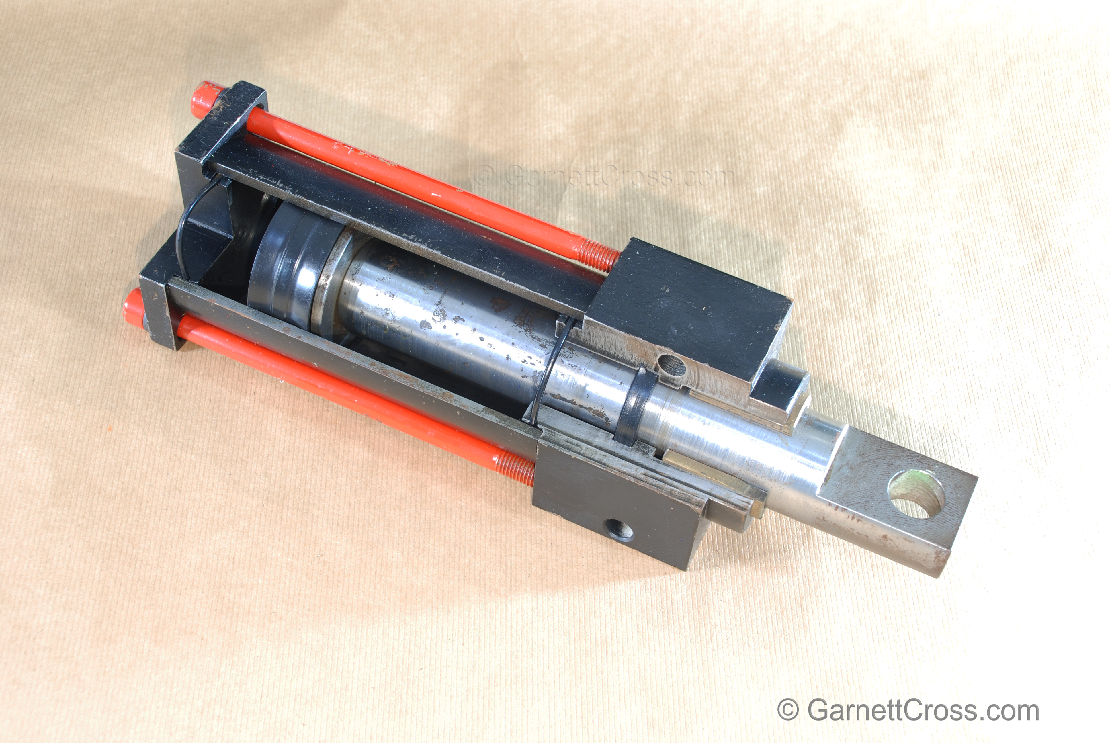
Oil Hydraulics Cylinder Note: This cylinder is poorly designed, the rod seal is behind the rod bushing, preventing lubrication to the rod bush and no rod wiper seal on the rod is present to keep contaminants out of the rod bushing. | |
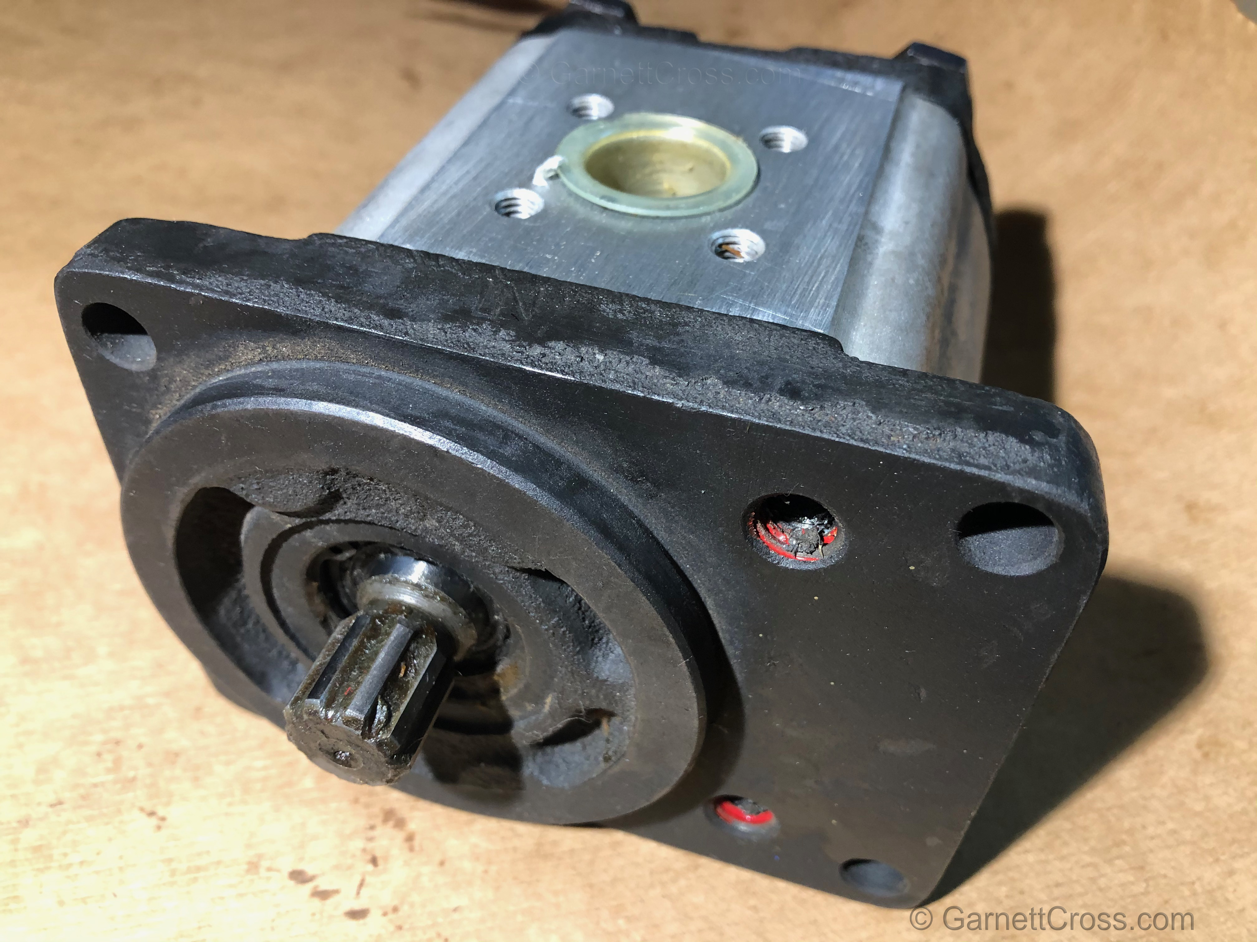
Hydraulic Gear Pump | |
Oil Hydraulics Gear Pump.
| |
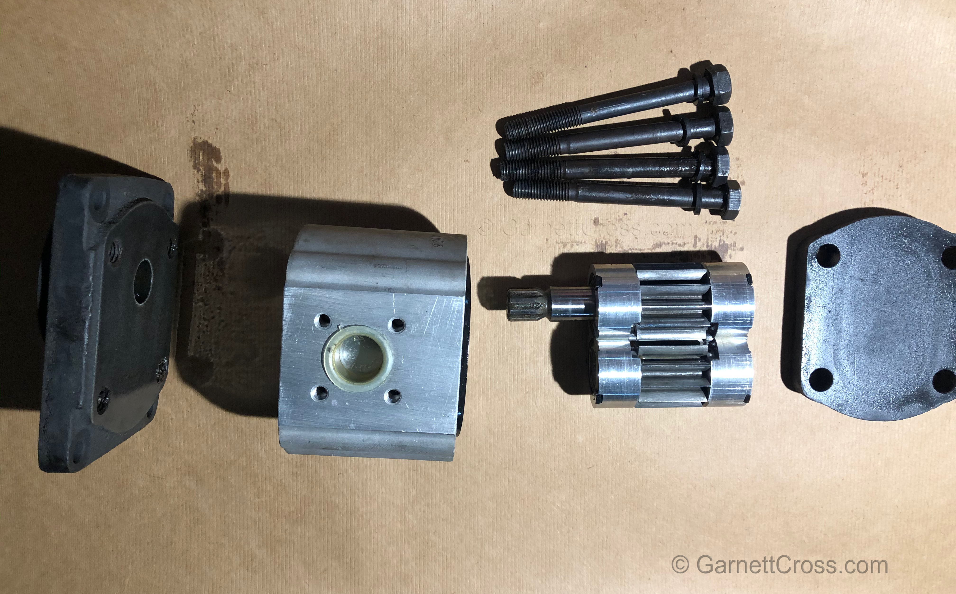
Oil Hydraulics Gear Pump disassembled.
| |
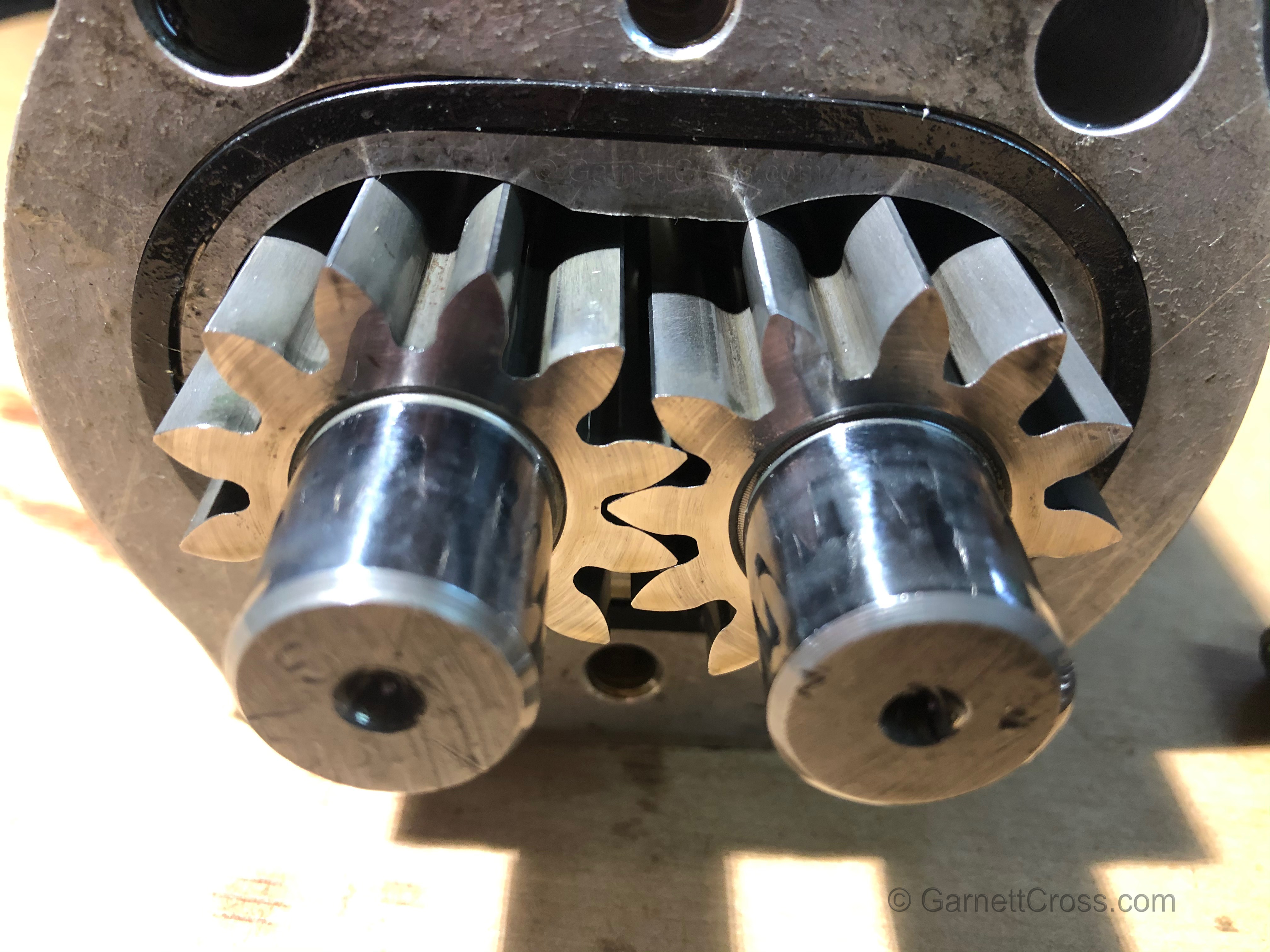
Hydraulics Gear Pump gears Note: The oil is moved in the hollows of the teeth around the outside of each gear as the pump turns. | |
Hydraulic Hoses and Tubing | |
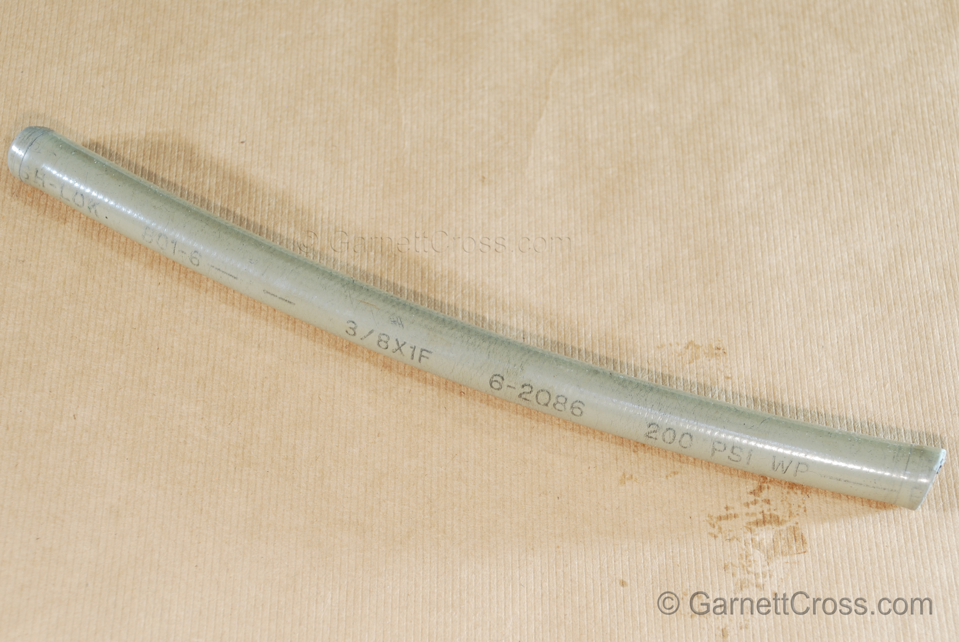
Oil Hydraulics Push Lock Hose (Push-Lok) Note: manufacture date is 2nd Quarter of 1986(2Q86) which has expired after the 5 year warranty. | |
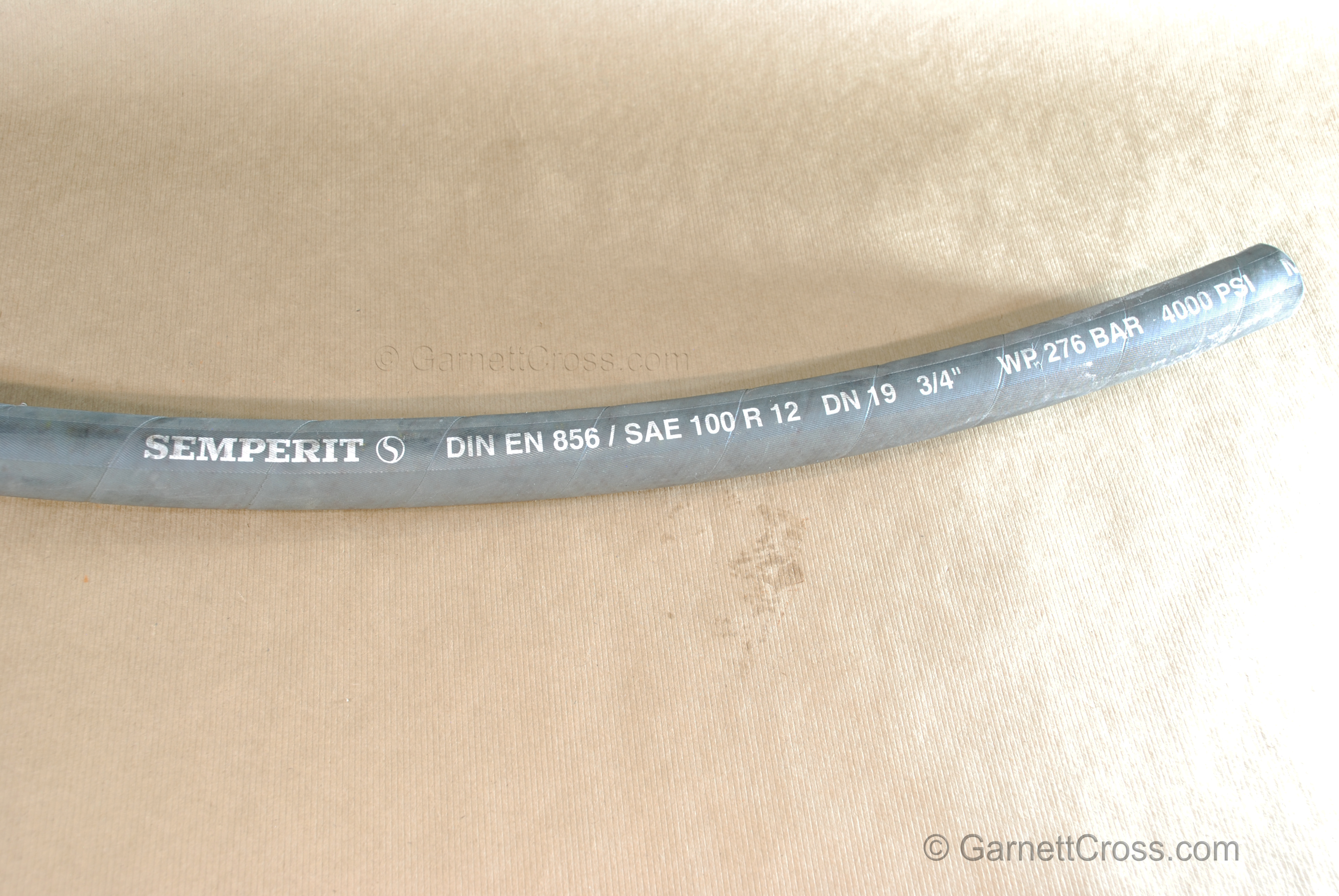
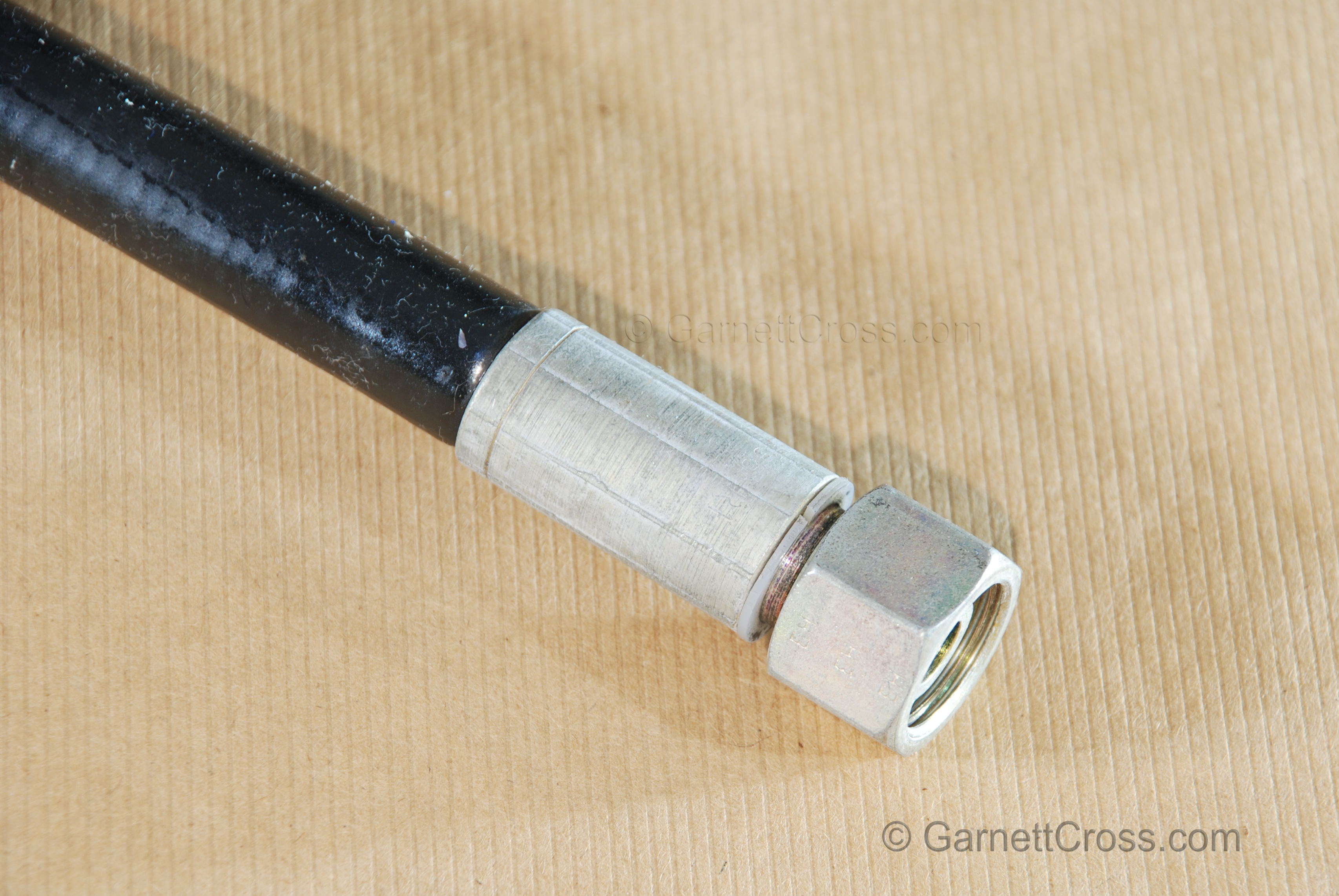
Oil Hydraulics Rubber Hose Note: manufacture date is not visible. The manufacture date must always be visible on installed hoses. | |
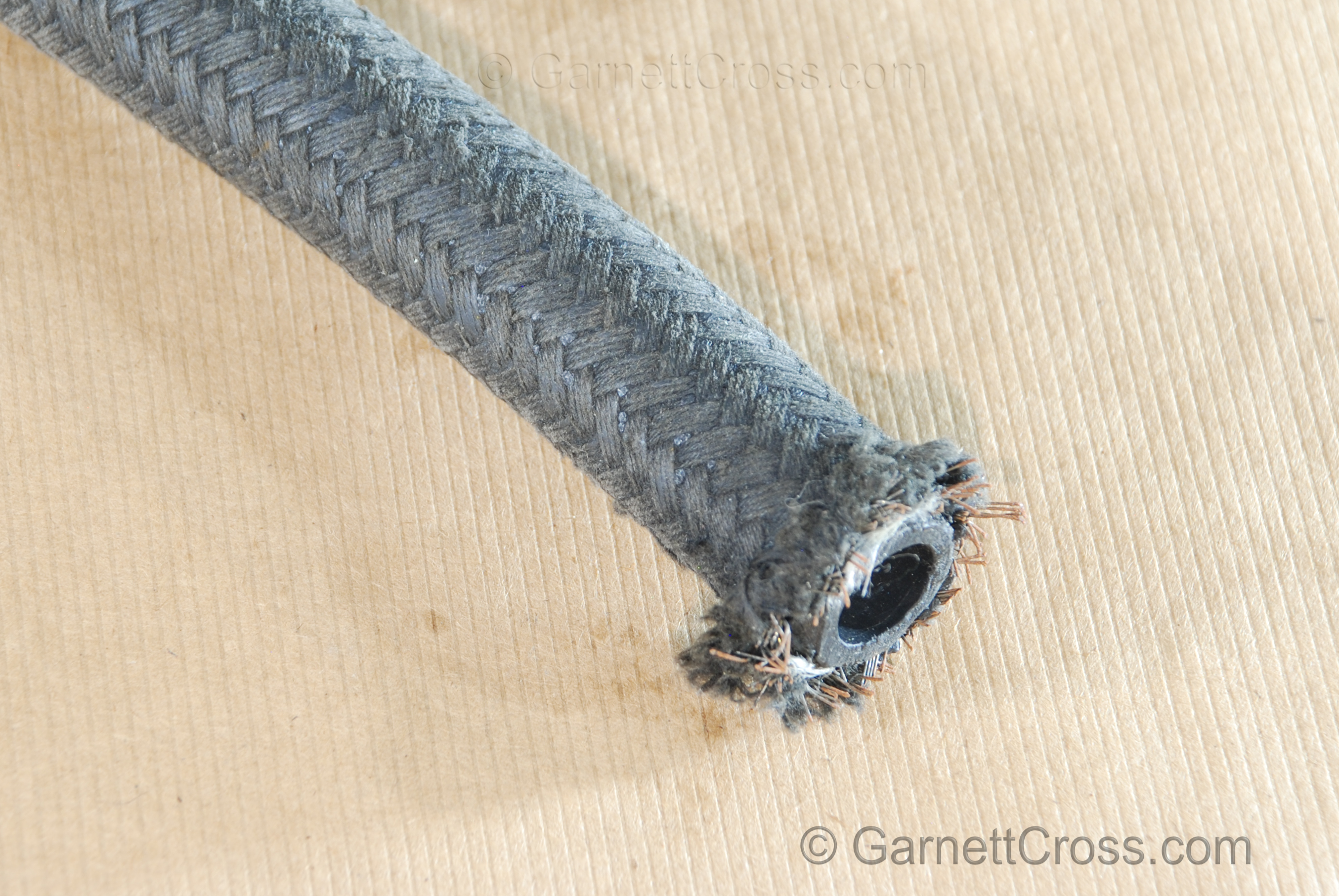
Oil Hydraulics Rubber Hose Double Braided reinforcing and swage fitting. Note: Never reuse a section of a host that has previously been compromised. | |
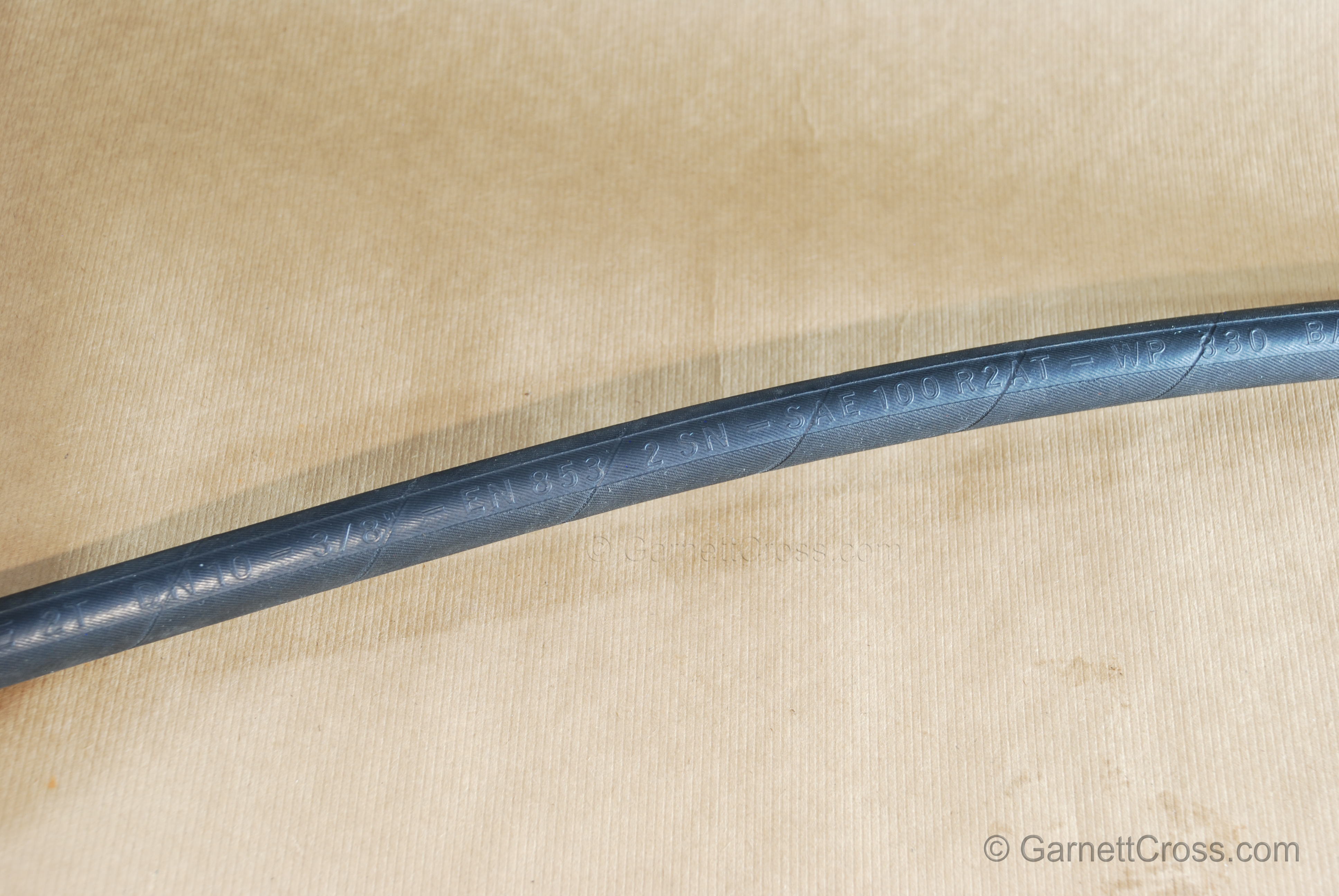
Oil Hydraulics Rubber Hose Embossed details Note: manufacture date is not visible. The manufacture date must always be visible on installed hoses. | |
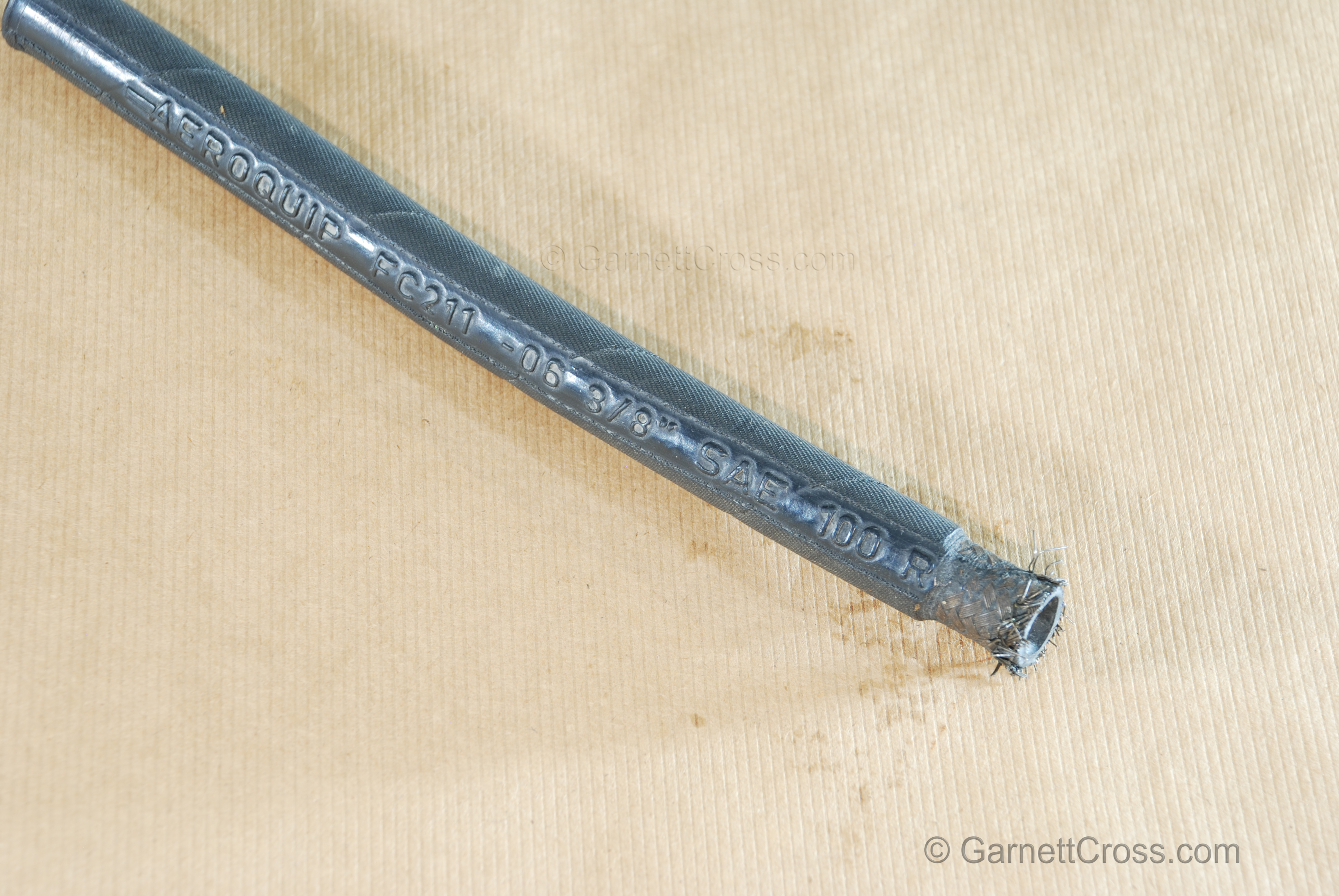
Oil Hydraulics Rubber Hose End Skived Note: No manufacture date is visible. The manufacture date must always be visible on installed hoses. | |
Oil Hydraulics Rubber Hose Skived with 4 spiral wire reinforcing. Note: Always measure the depth of the fitting and mark the hose to ensure the hose inserted to full depth. | |
Oil Hydraulics Rubber Hose Swaged Fitting Both skived and no-skived types are available, no lubricant must be applied to fittings when being assembled. Rubbing alcohol may be used as a lubricant. | |
Oil Hydraulics Rubber Hose Textile Braiding (Cotton braiding). SAE-100 R5. Note: May be used for oil applications, when used for air - air will effuse through the inner tube and pass through the rubber covering over the reinforcing escaping through the textile covering not causing any blistering to outing covering. Rubber covered hoses must not be used for air or gas applications which may result in blistering of the outer rubber covering as air effuses through the inner tube. the R5 hoses the outer diameter of the inner tube is measured as the hose diameter. | |
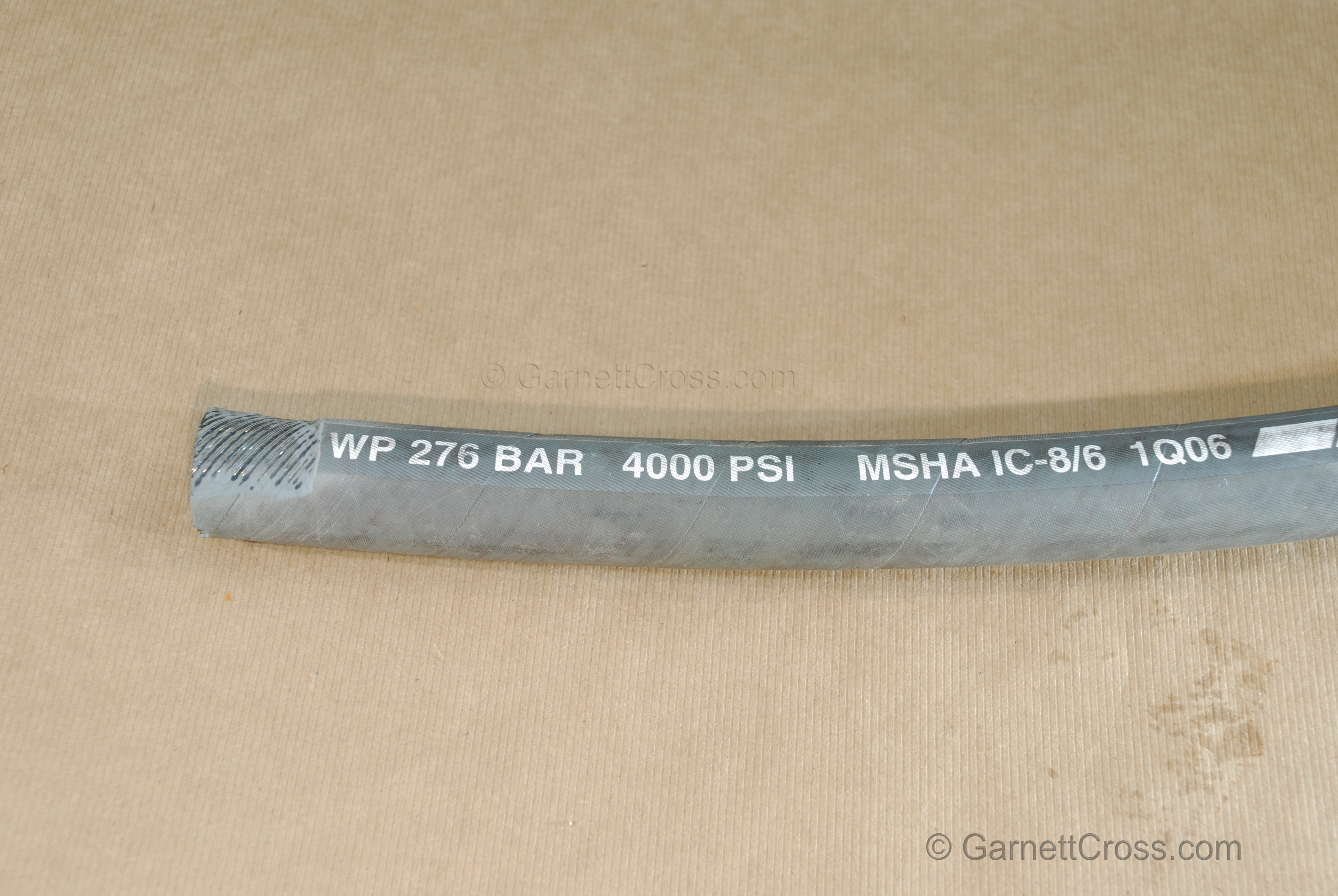
Oil Hydraulics Rubber Hose with Spiral Wire Rubber removed to expose reinforcing Note: manufacture date is first quarter 2006. (1Q06) | |
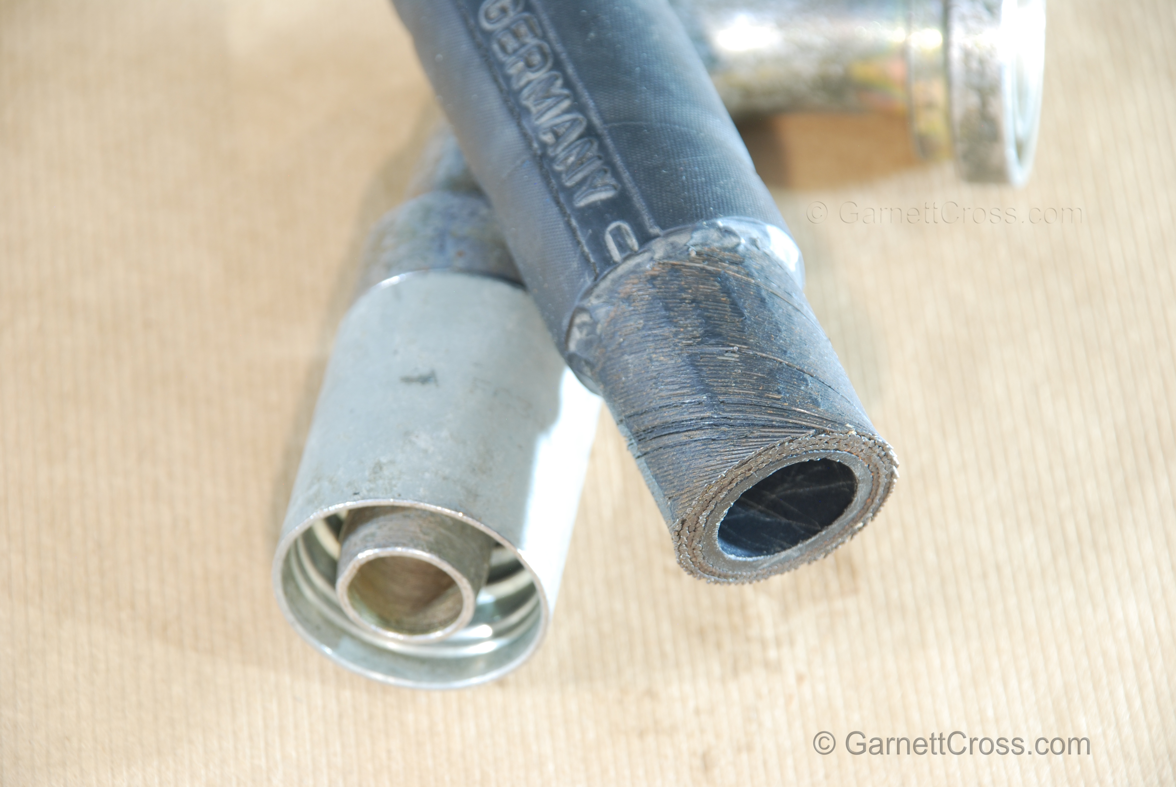
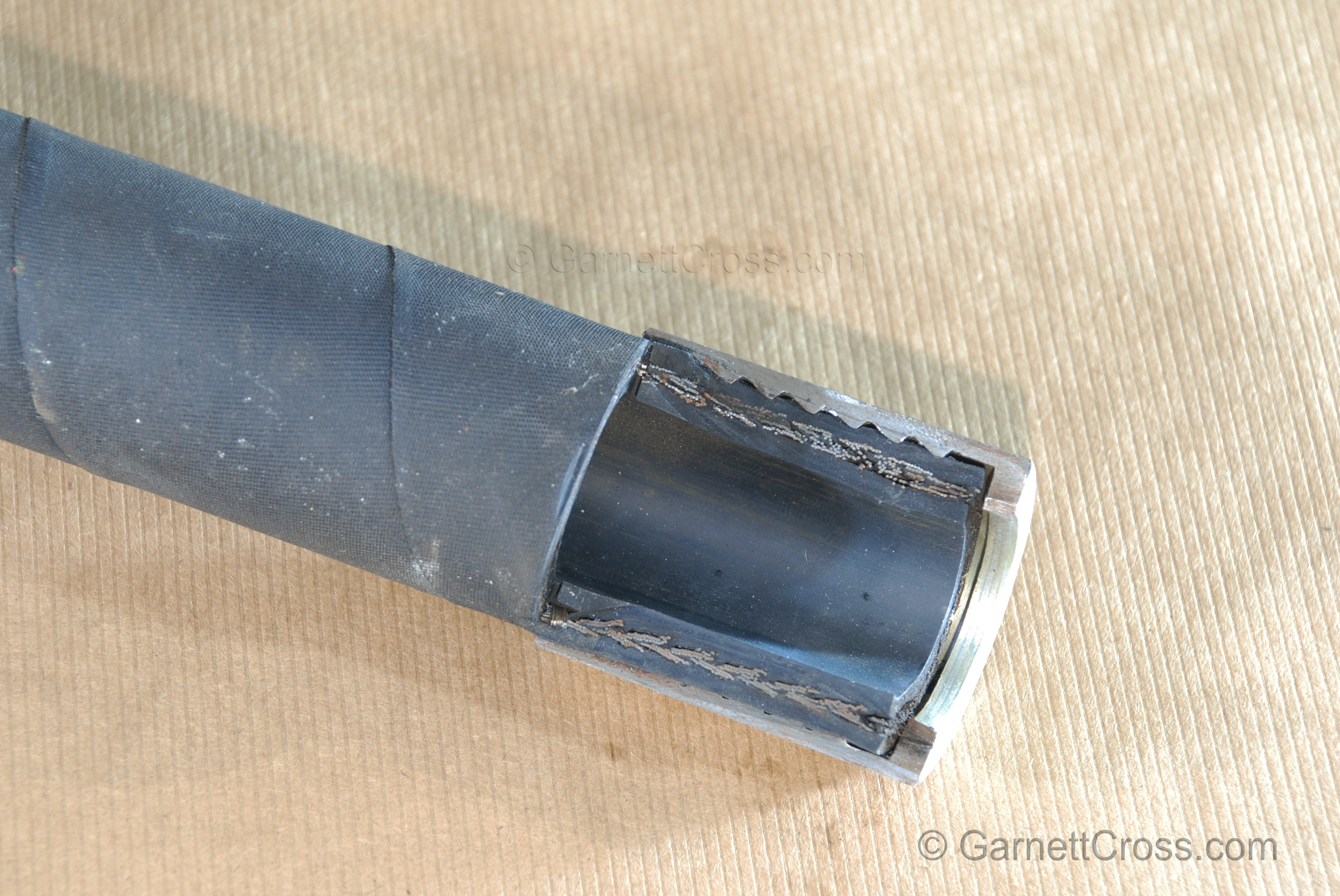
Oil Hydraulics Rubber hose with braided wire reinforcing and swaged fitting cross section - insert removed. | |
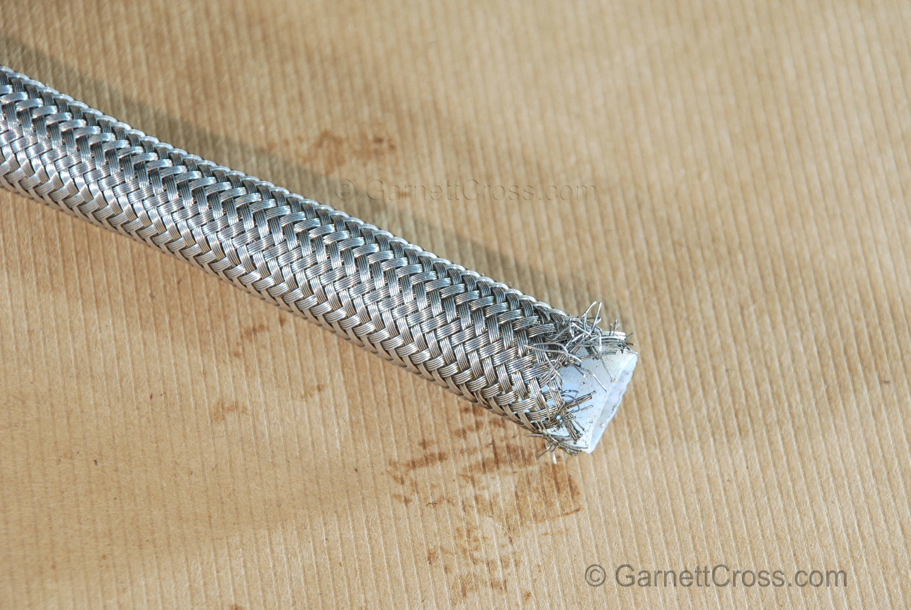
Oil Hydraulics Stainless Braided Hose Note: This type of hose normally used for steam but can be used for oil hydraulics. | |
Oil Cleanliness Testing | |
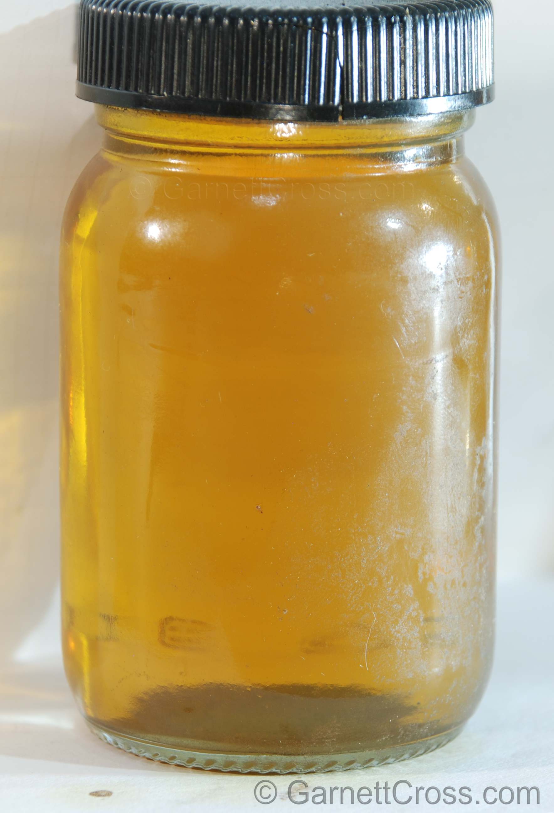
Oil Hydraulic - New oil with contaminants gravitated to the bottom. Note: All oil must be filtered to at least 10 micron before being pumped in to the reservoir.https://garnettcross.com/?page=resources#oil_cleanliness | |
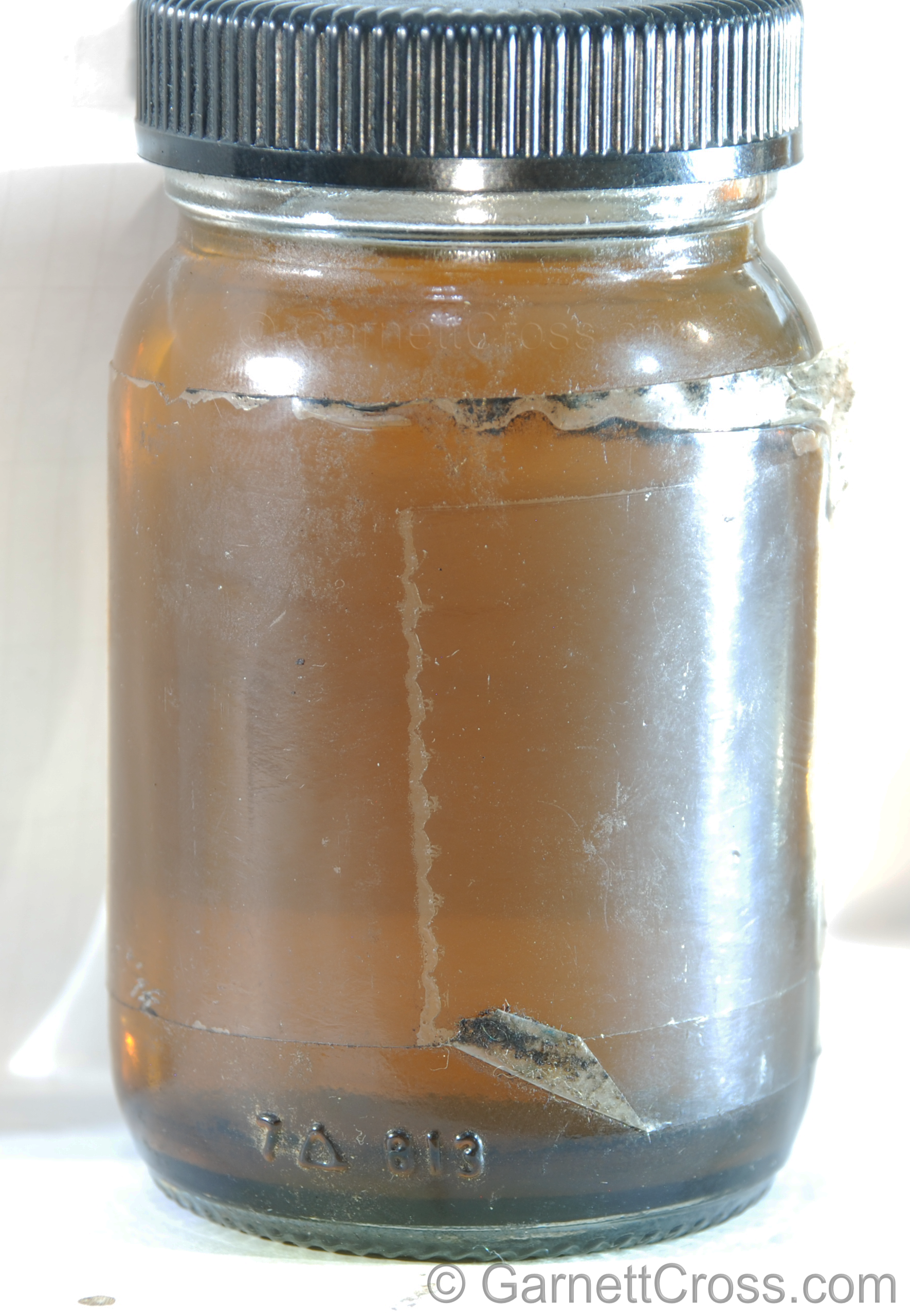
Oil Hydraulic Fluid contaminated with dirt (Settled at the bottom). | |
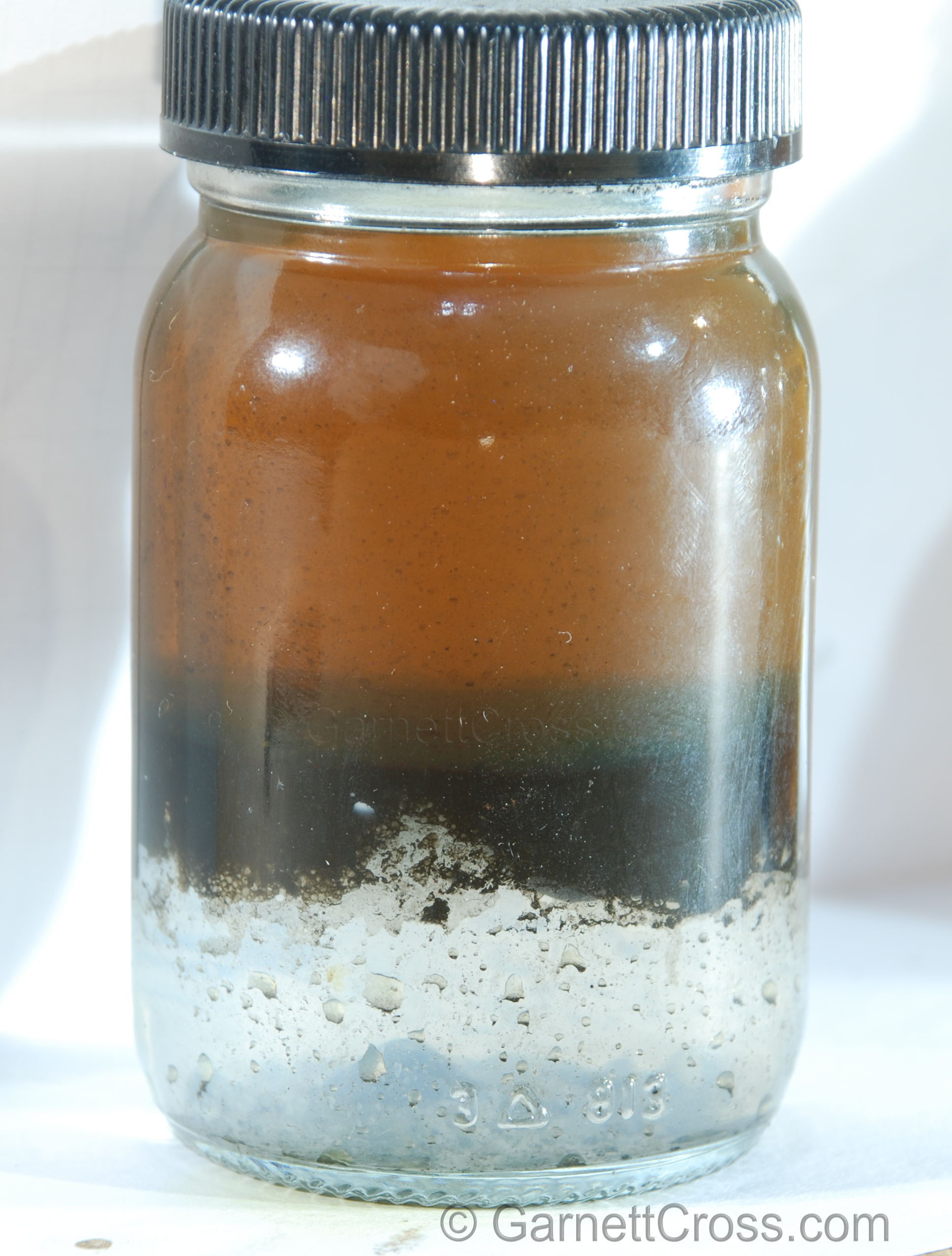
Oil Hydraulic Fluid contaminated with dirt and water. | |
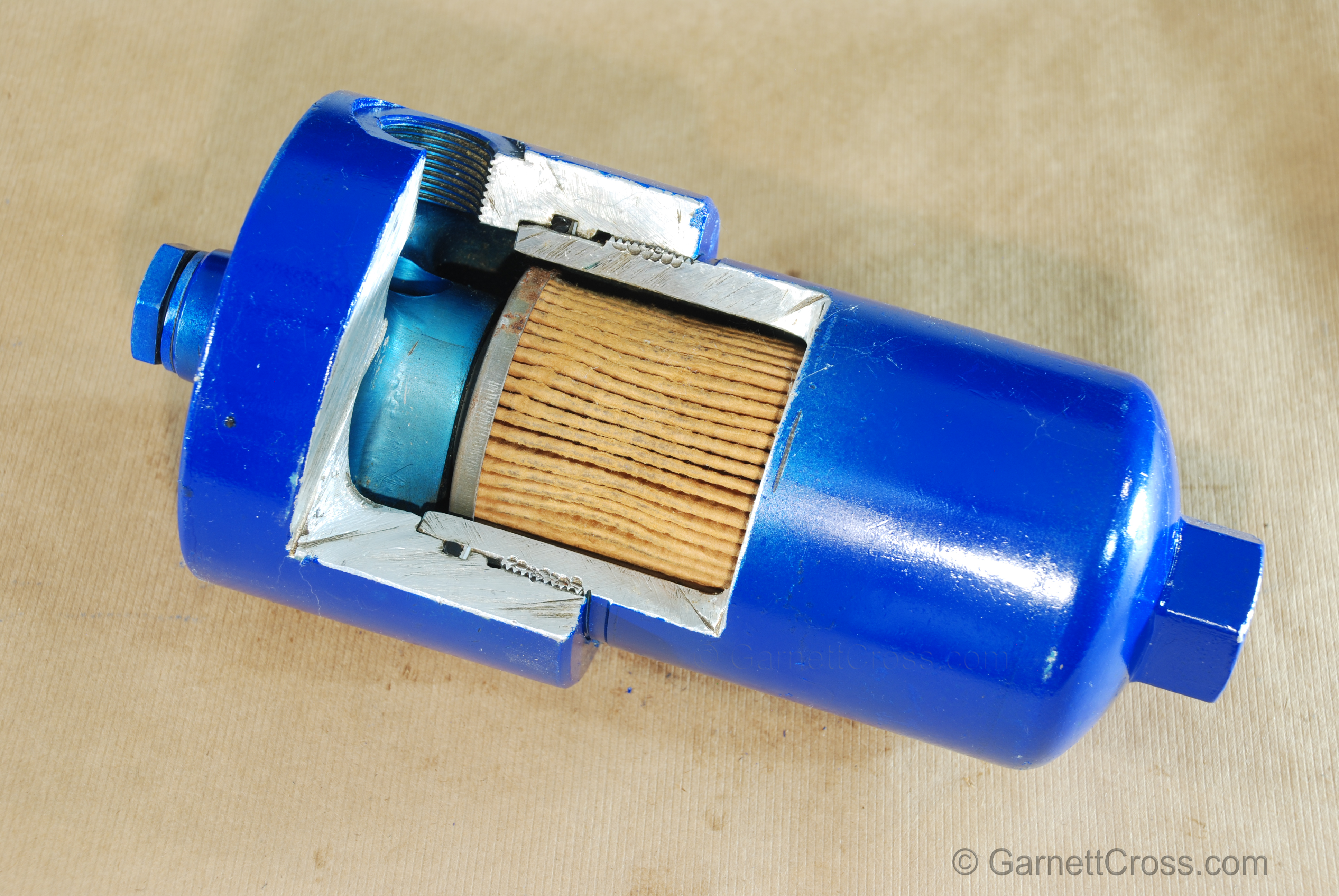
Oil Filters | |
Oil Hydraulics Oil Filter cross section. Note: Filters must be sized to 1.5 times the flow rate to pass through the filter, to avoid collapsing the element. | |
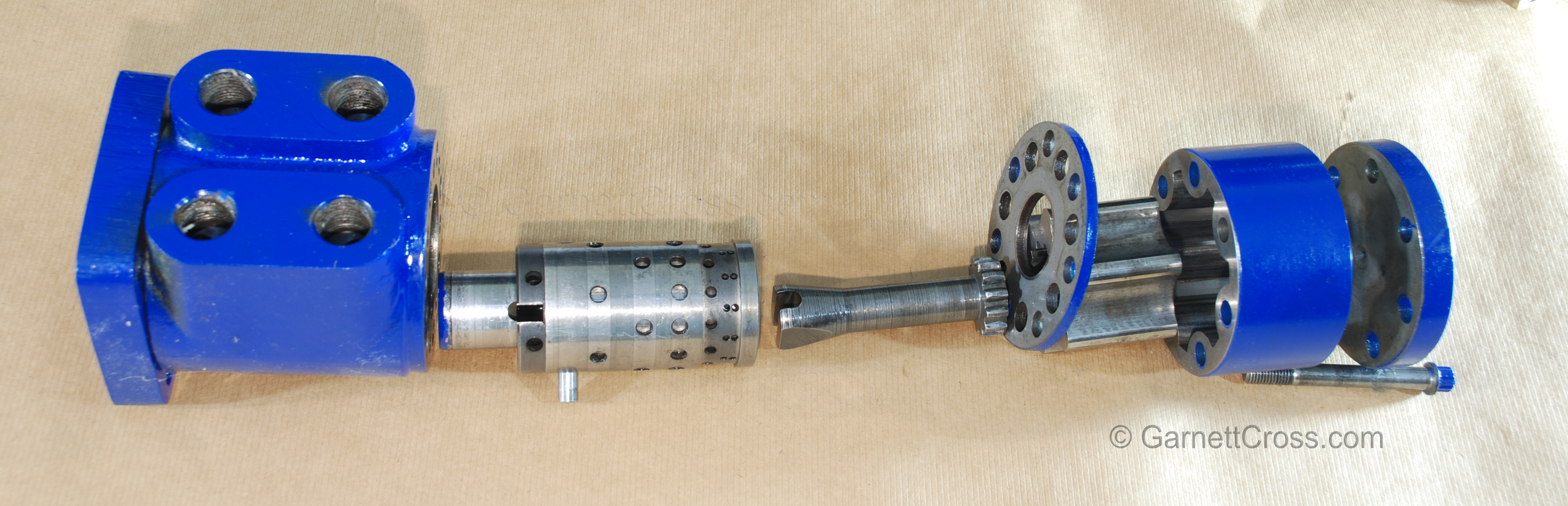
Oribtrol Steering Valve | |
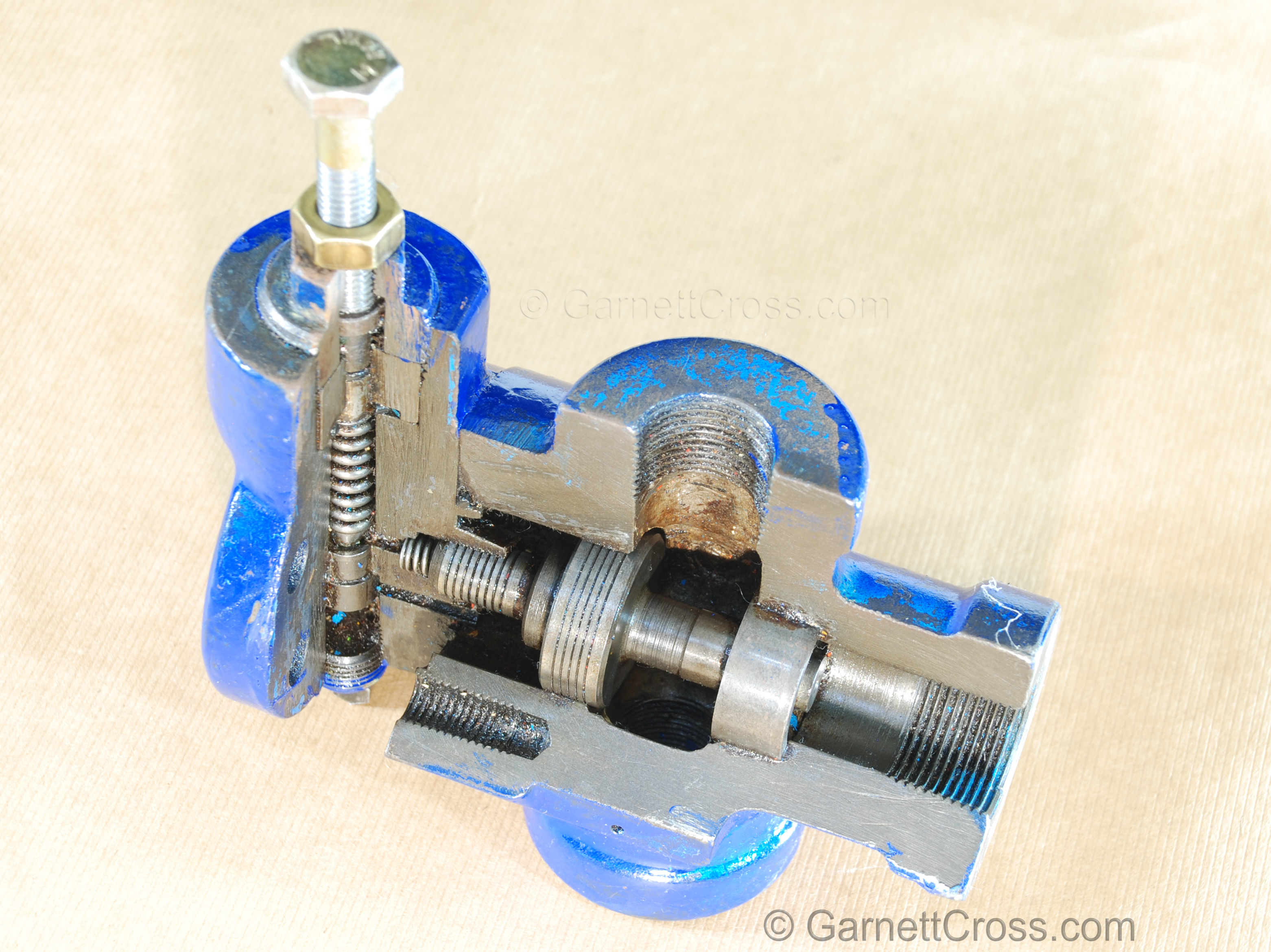
Oil Hydraulics Orbitrol Steering Valve The Orbitrol Steering Valve may be used as a directional valve for cylinders. Works very well for a workshop press. The press is able to precisely control pressing, as an example pressing bearings into bearing housings. | |
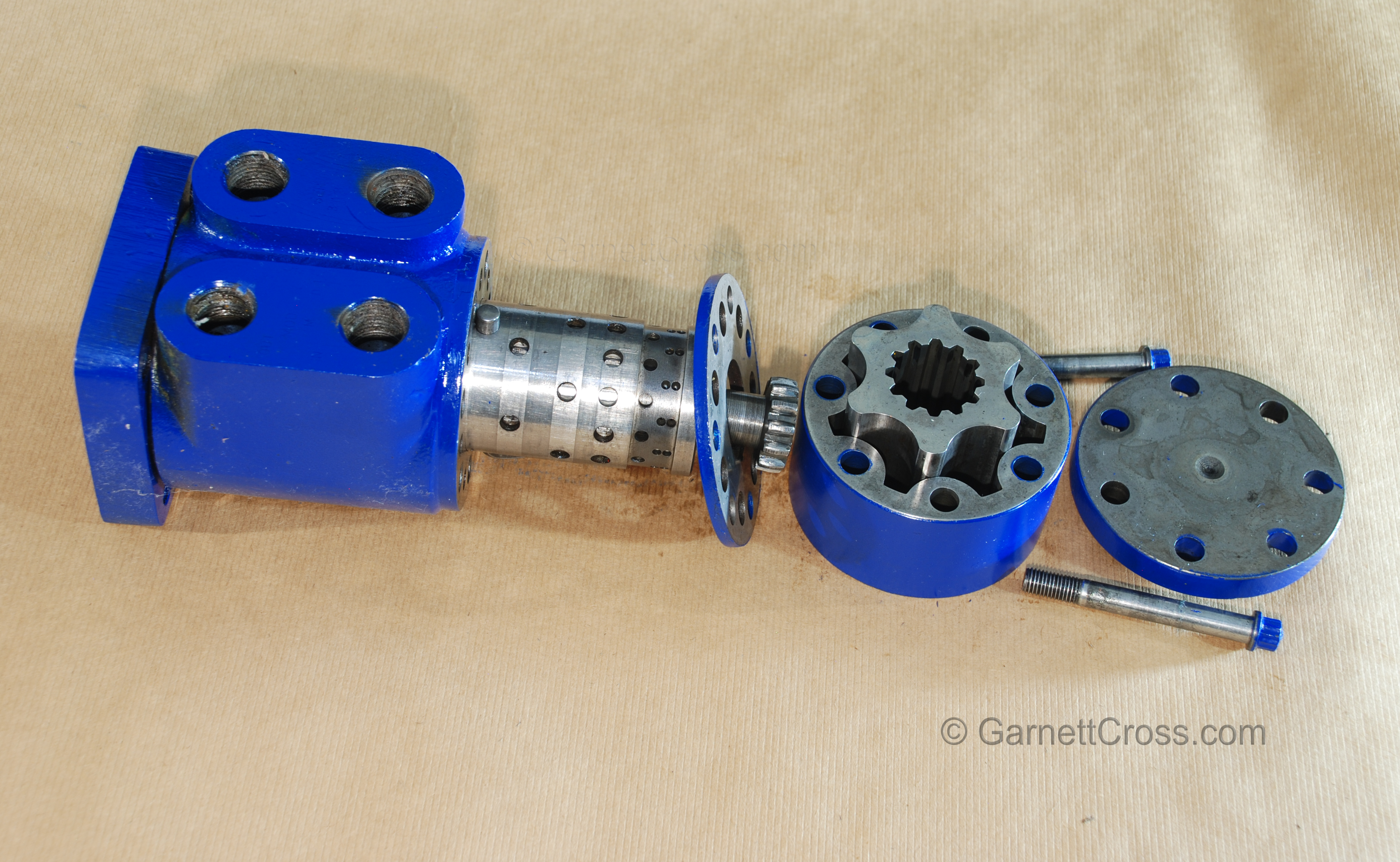
Oil Hydraulics Orbitrol Steering Valve For this model the individual components are arranged as it should be assembled. Ports positioned to the top, pin standing vertical through the directional control valve, rotor shaft slot inserted vertically over the vertical pin, the rotor at the bottom with teeth straddling the top lobe of the rotor ring. Confirm configuration for the individual model being used. (Spacer ring not displayed) | |
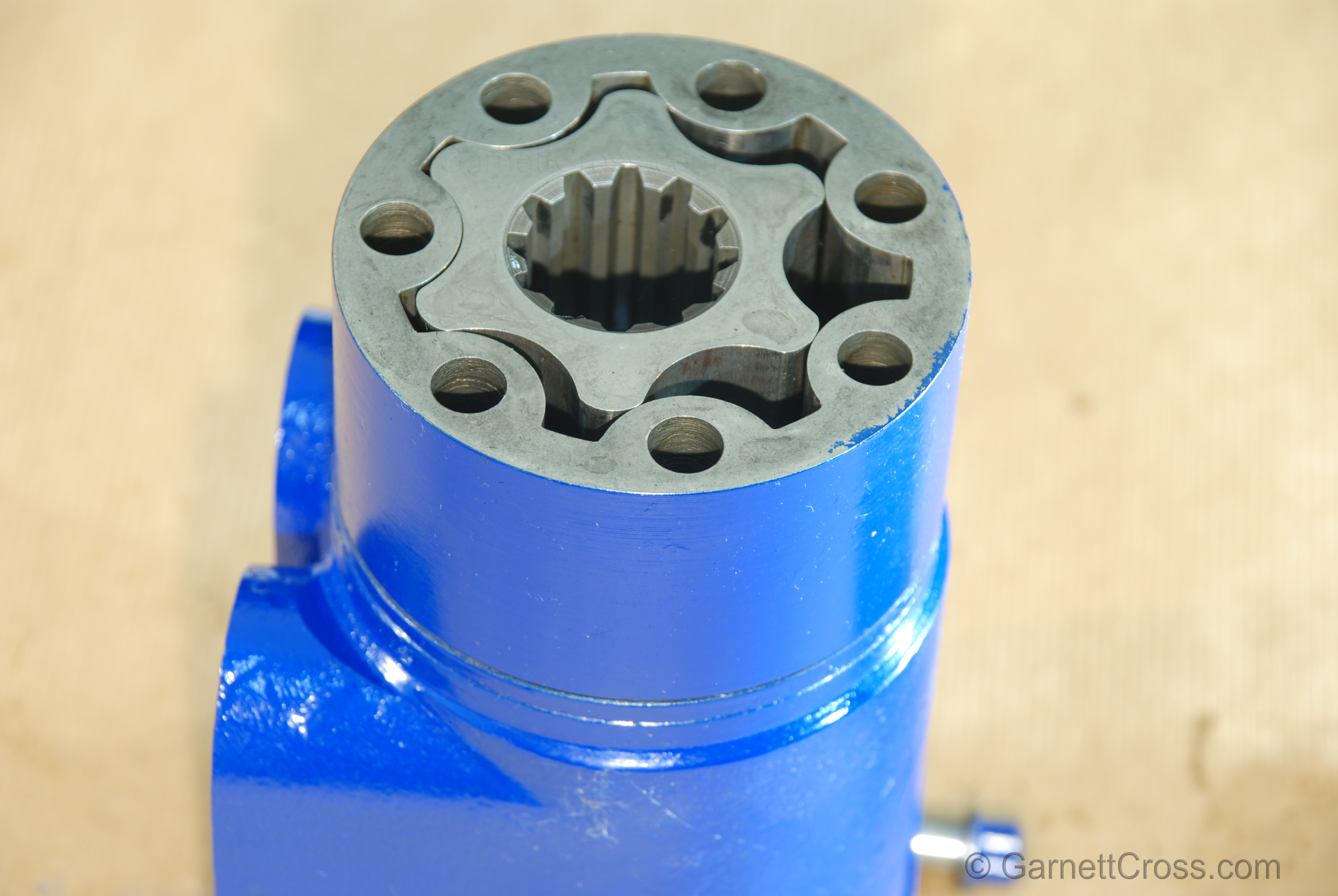
Oil Hydraulics Orbitrol Steering Valve Rotor in correct position for assembly. | |
Oil Hydraulics Orbitrol Steering Valve | |
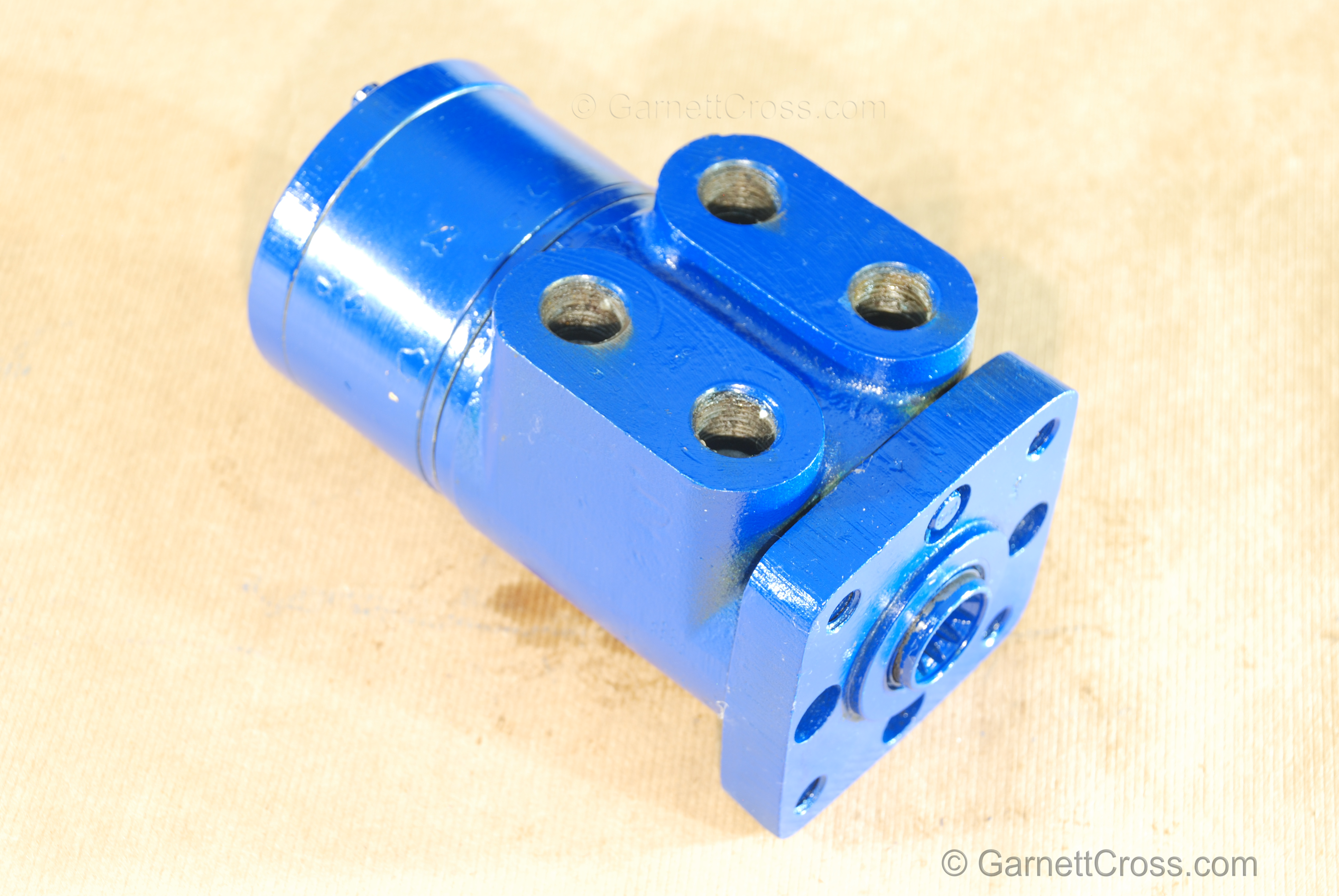
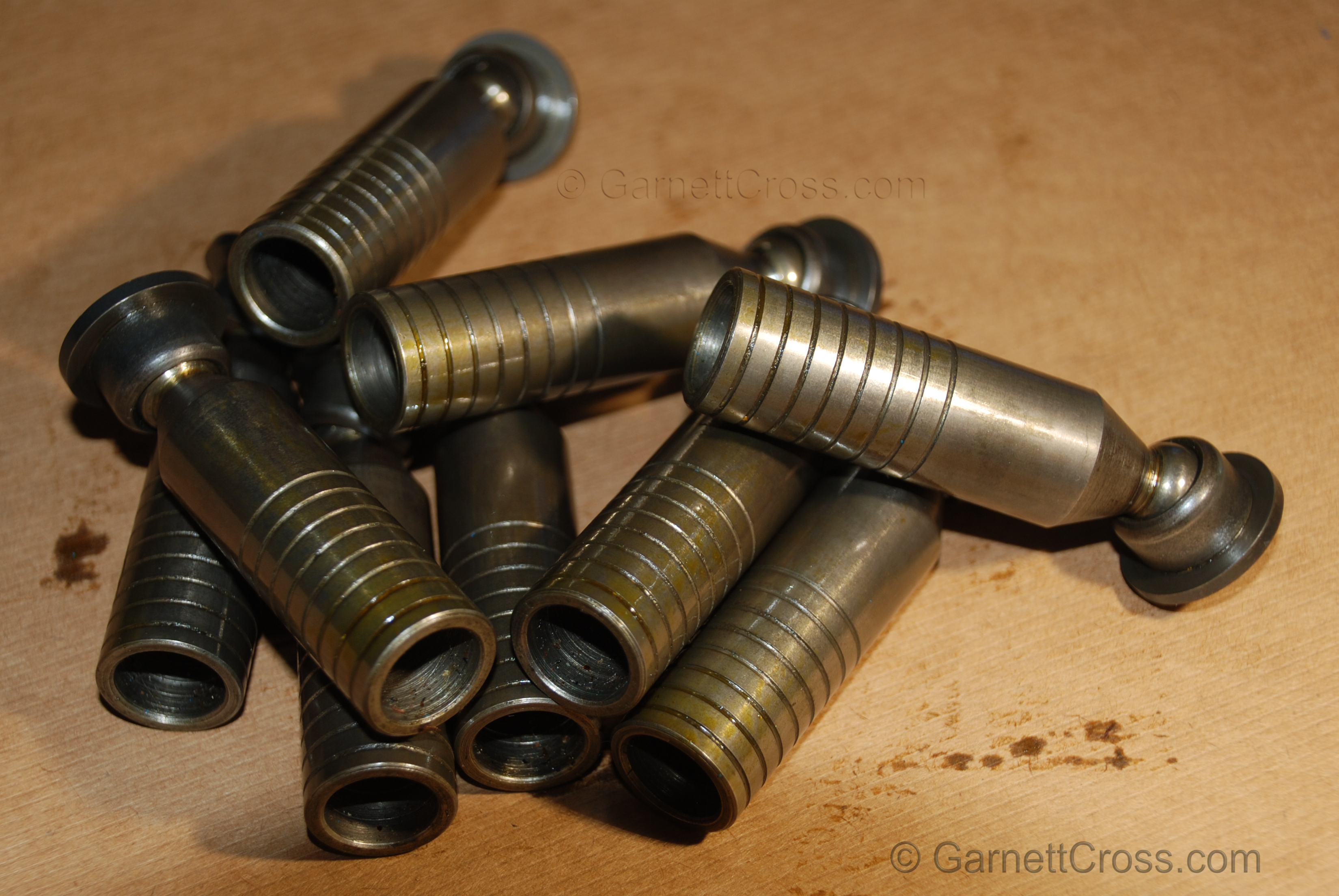
Piston Pump | |
Oil Hydraulics Piston Pump Pistons. Note the balancing grooves on the pistons. | |
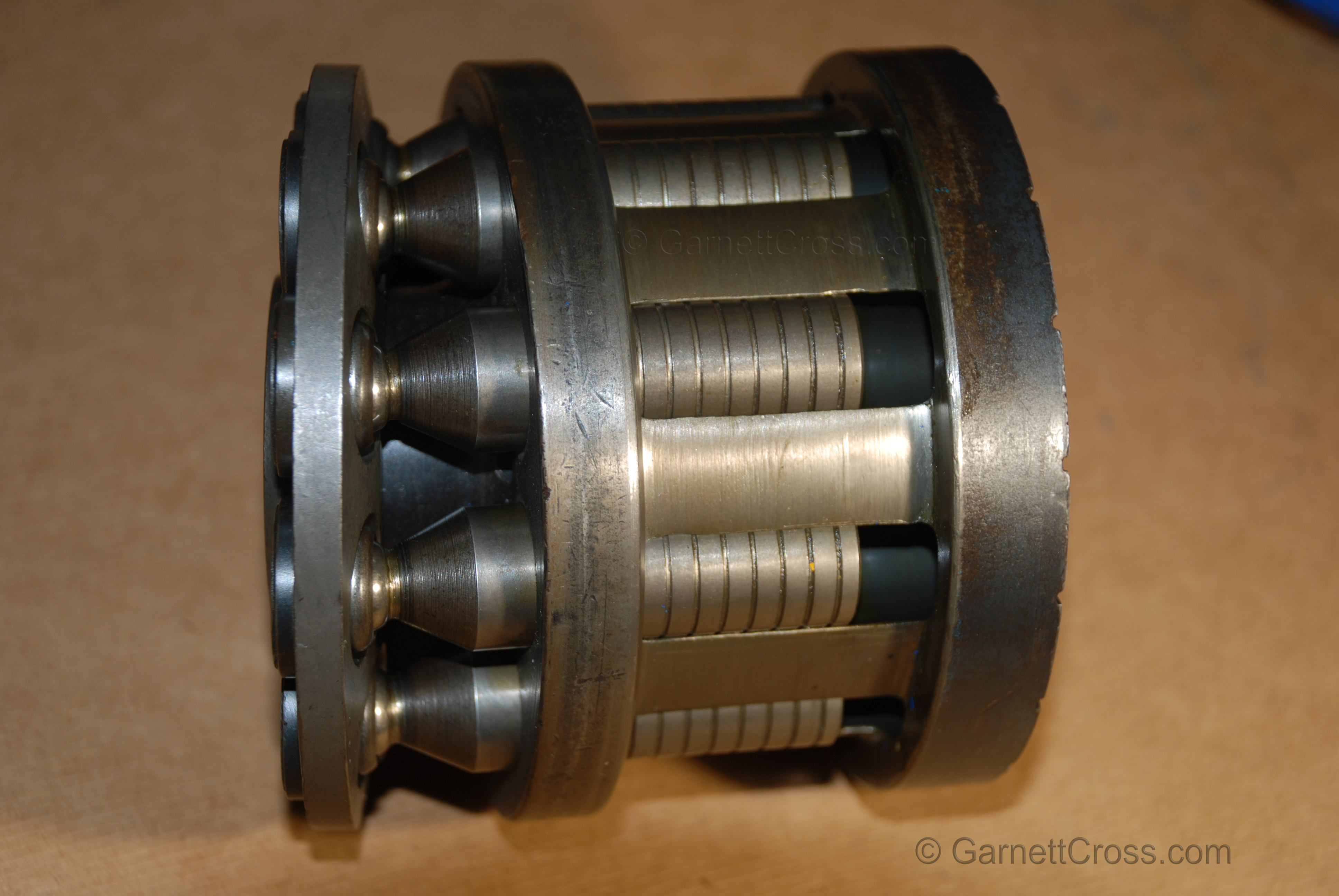
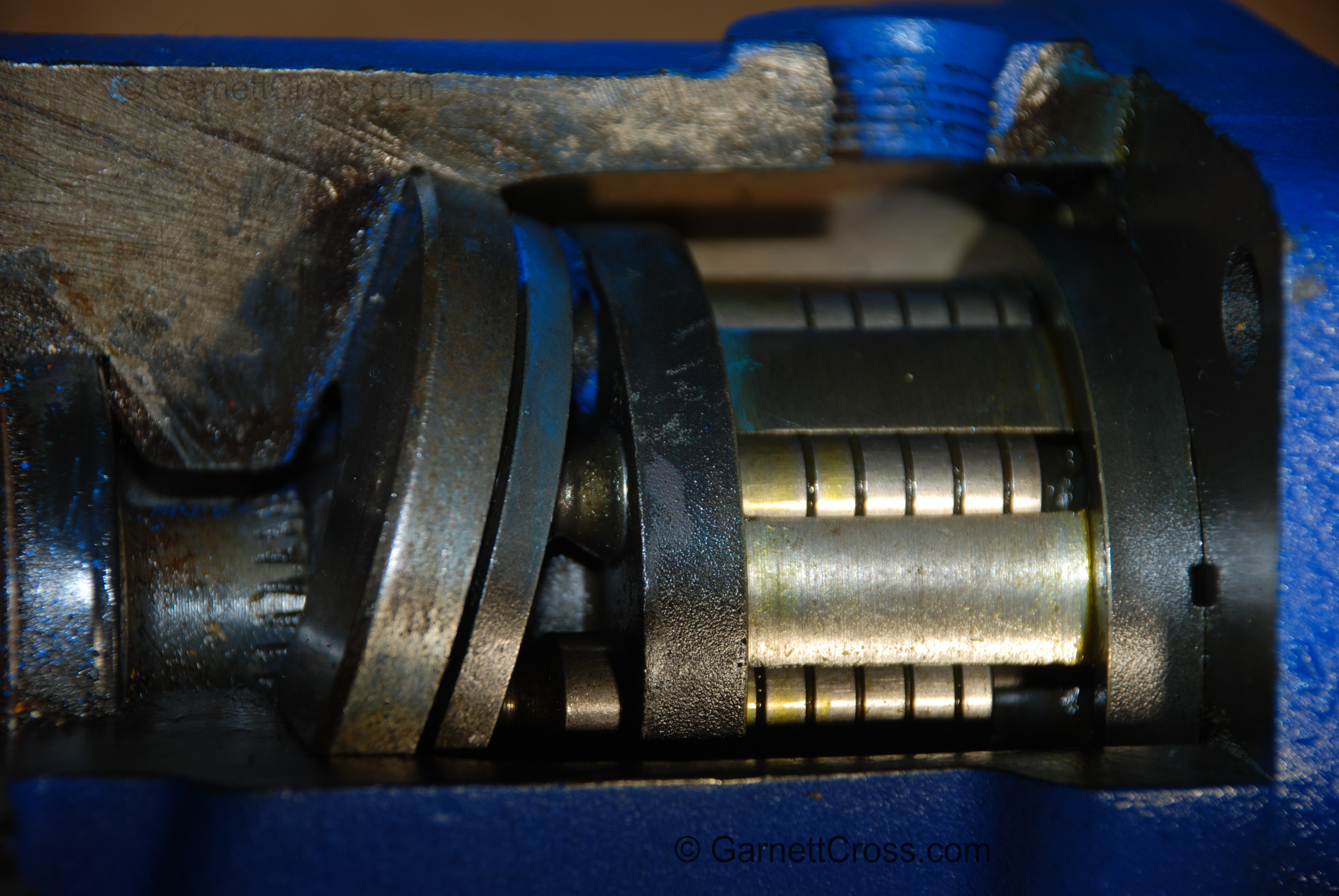
Oil Hydraulics Piston Pump Rotating Group with section cut-away to expose the pistons. | |
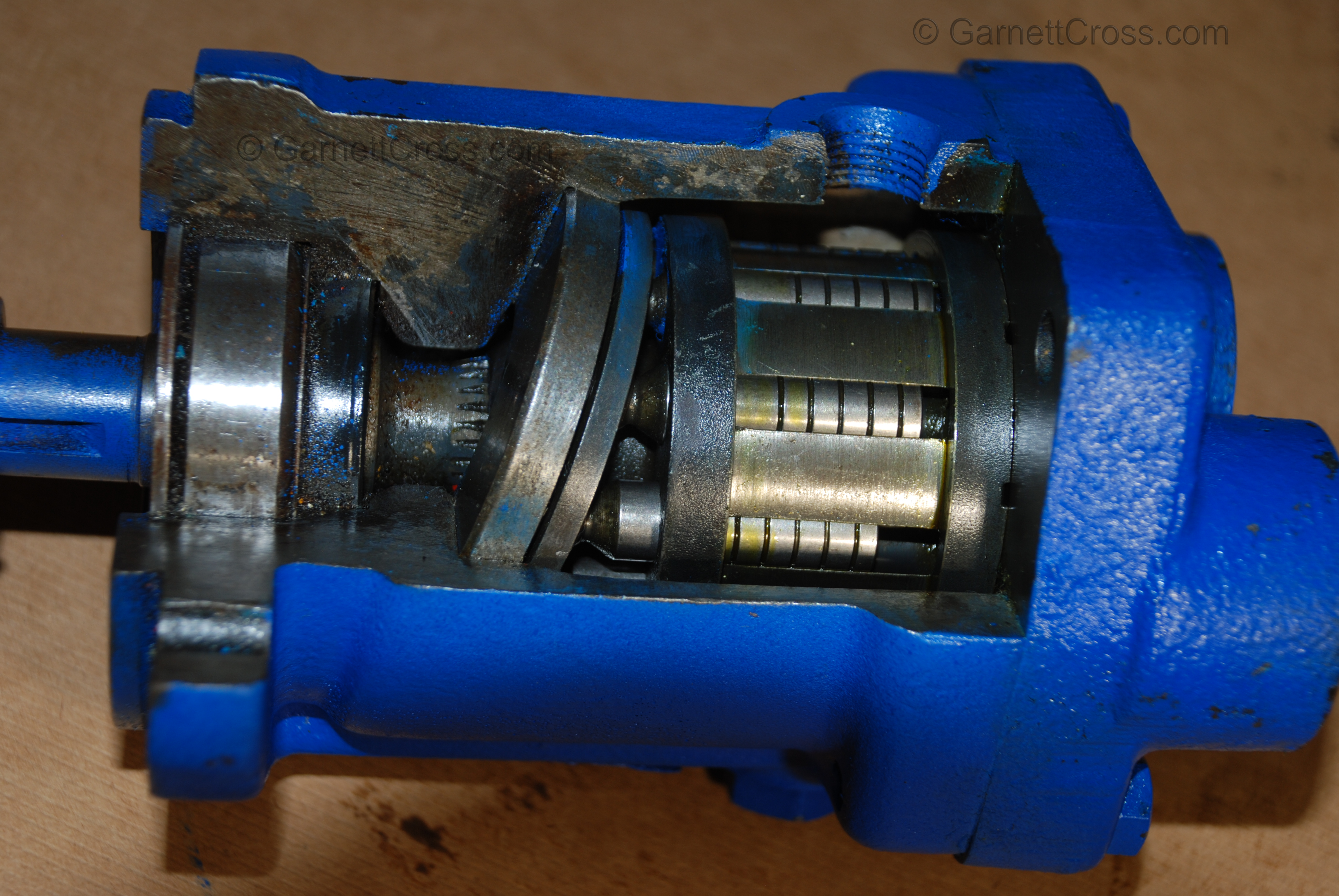
Oil Hydraulics Piston Pump with Cut-away to expose the Rotating Group, Shoe Piston Shoe Retainer Plate, Swash Plate, Shaft, Seal, Bearing and Circlip. | |
Oil Hydraulics Piston Pump with Cut-away to expose the Rotation Group, Show Piston Shoe Retainer Plate and Swash Plate. | |
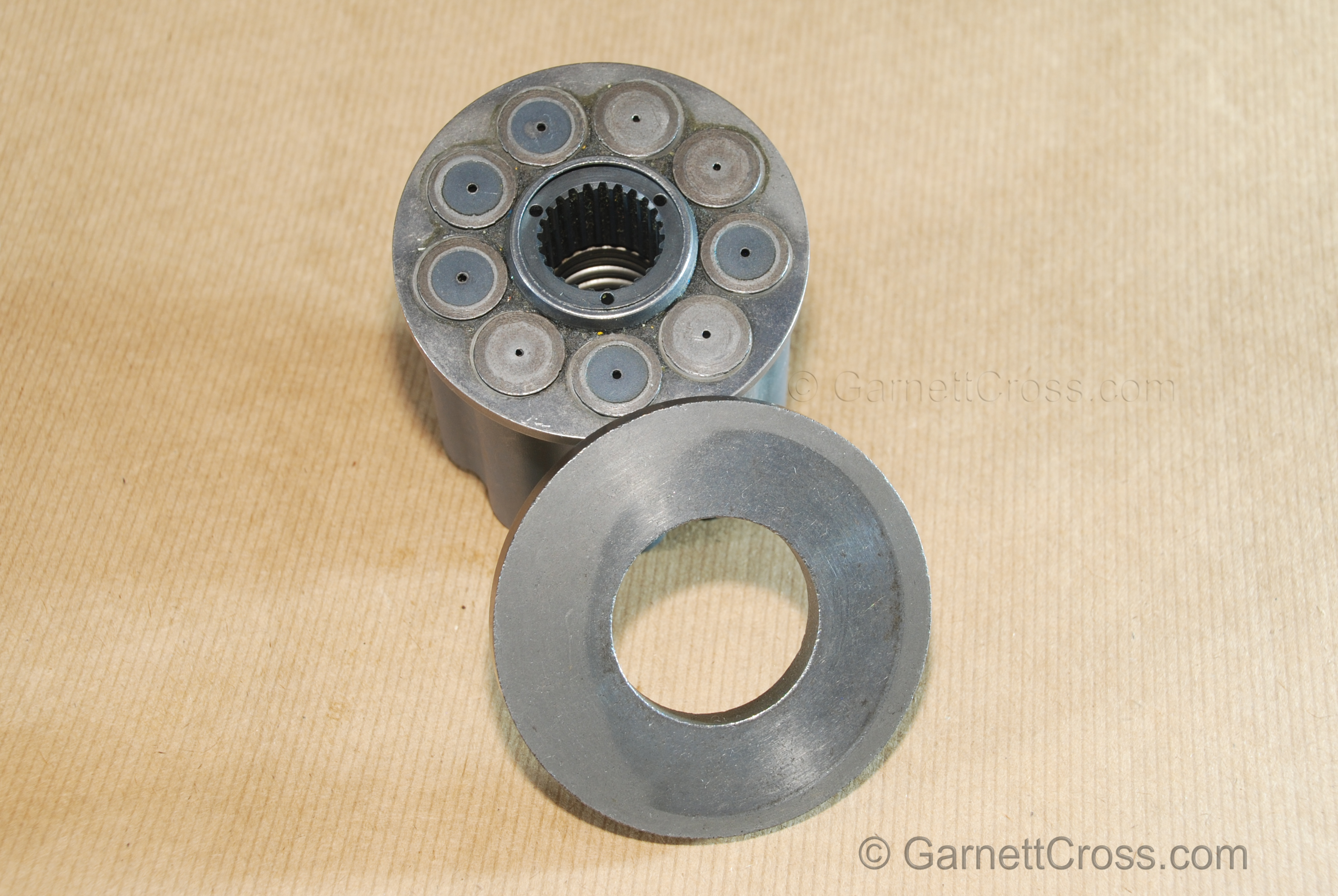
Oil Hydraulics Piston pump rotating group | |
Oil Hydraulics Piston pump rotating group Note: Signs of damage due to undersized intake pipe, flattened shoes and worn swash plate | |
Pressure Control Valves | |
Oil Hydraulics Relief Valve cross section - Vickers valve. | |
Servo Valve | |
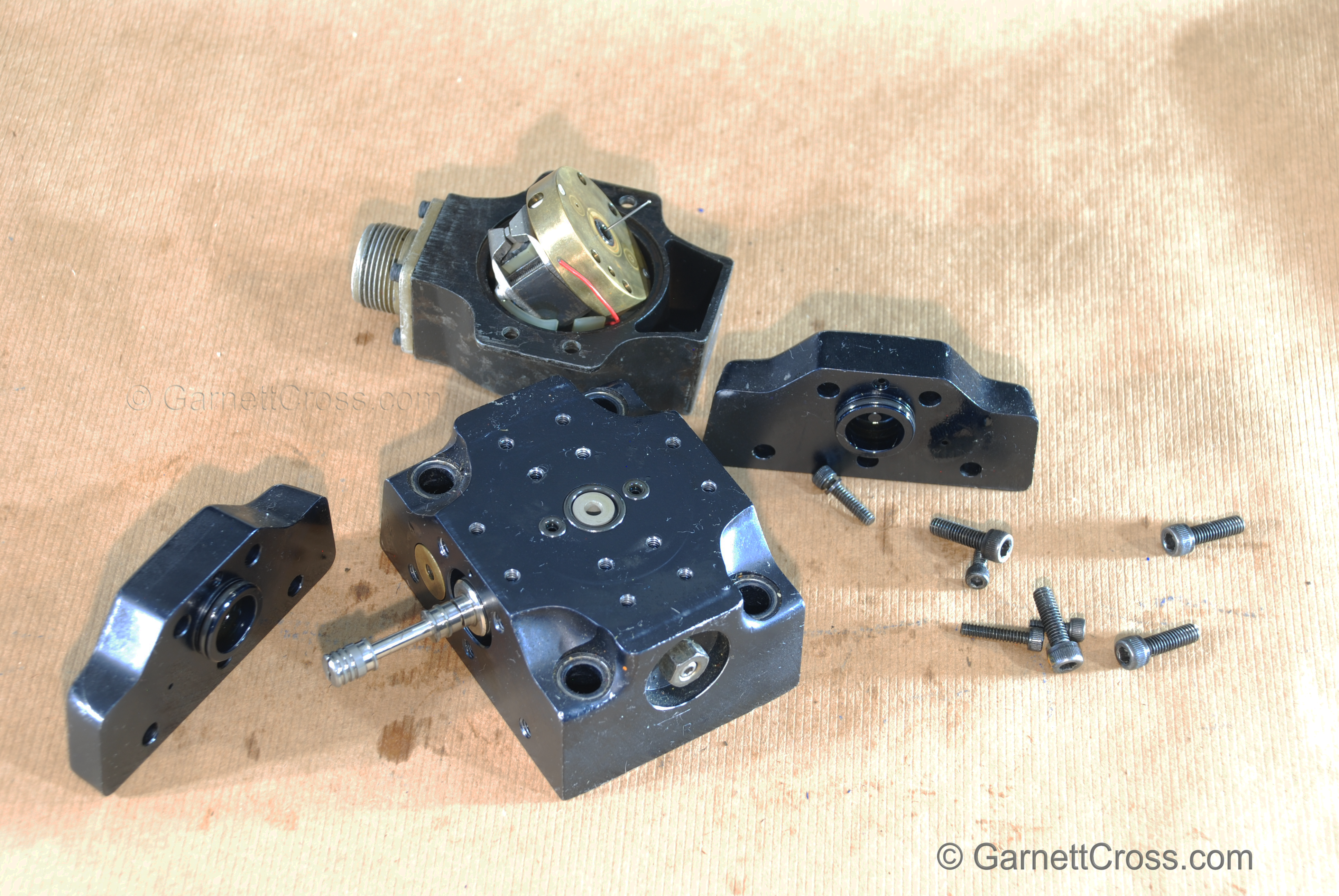
Oil Hydraulics Moog Servo Controlled Valve disassembled. Note: Each servo valve must have a dedicated 3 micron filter in the pressure supply line for the valve. | |
Vane Pump | |
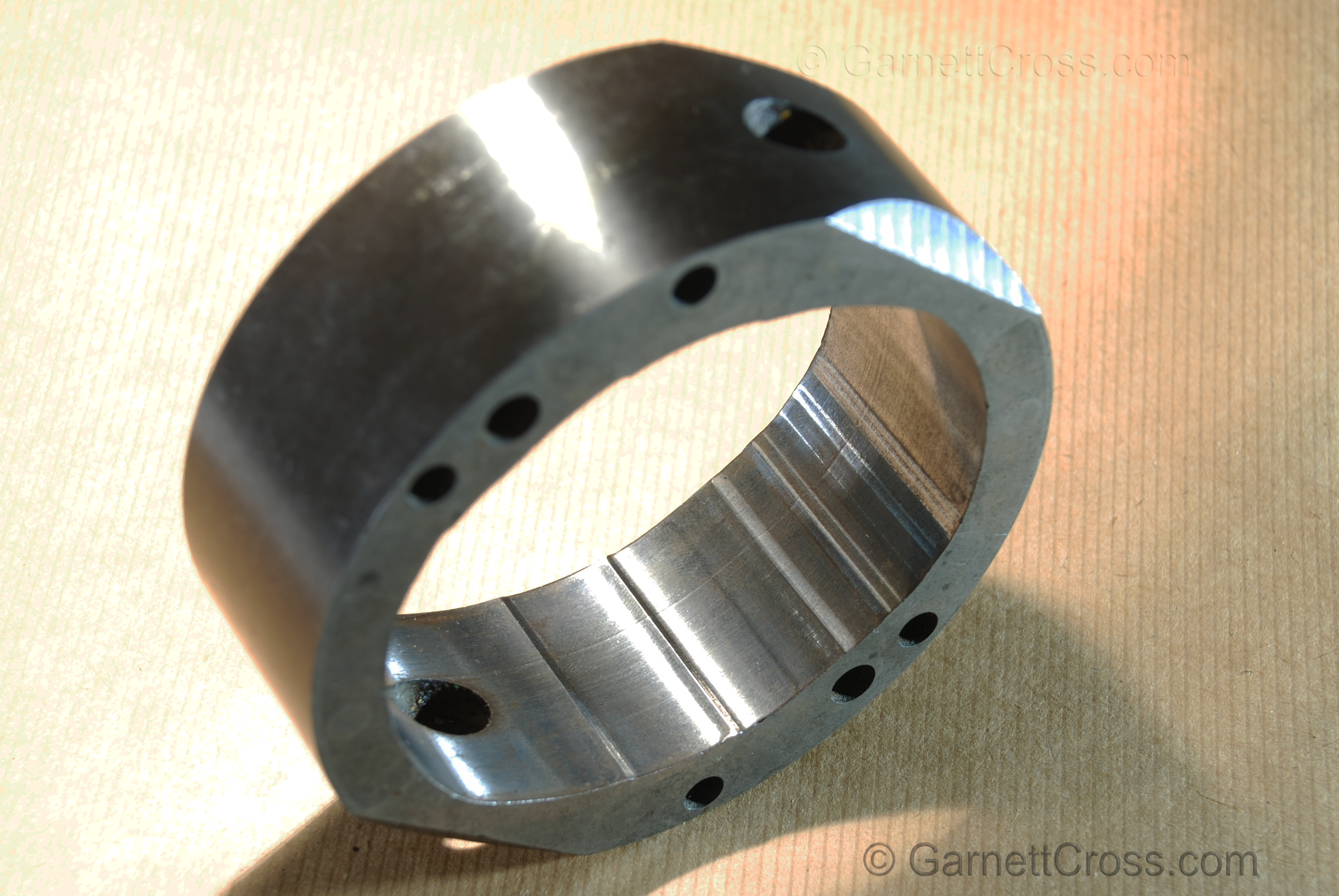
Oil Hydraulics Vane Pump Cam Ring showing signs of cavitation A larger pump had been installed without increasing the size of the intake pipe. Pump was in operation for 5 days only. | |
Oil Hydraulics Vane Pump Cam Ring with first signs of cavitation at the lower inner surface of the cam ring. Pump was in operation for 5 days only. | |
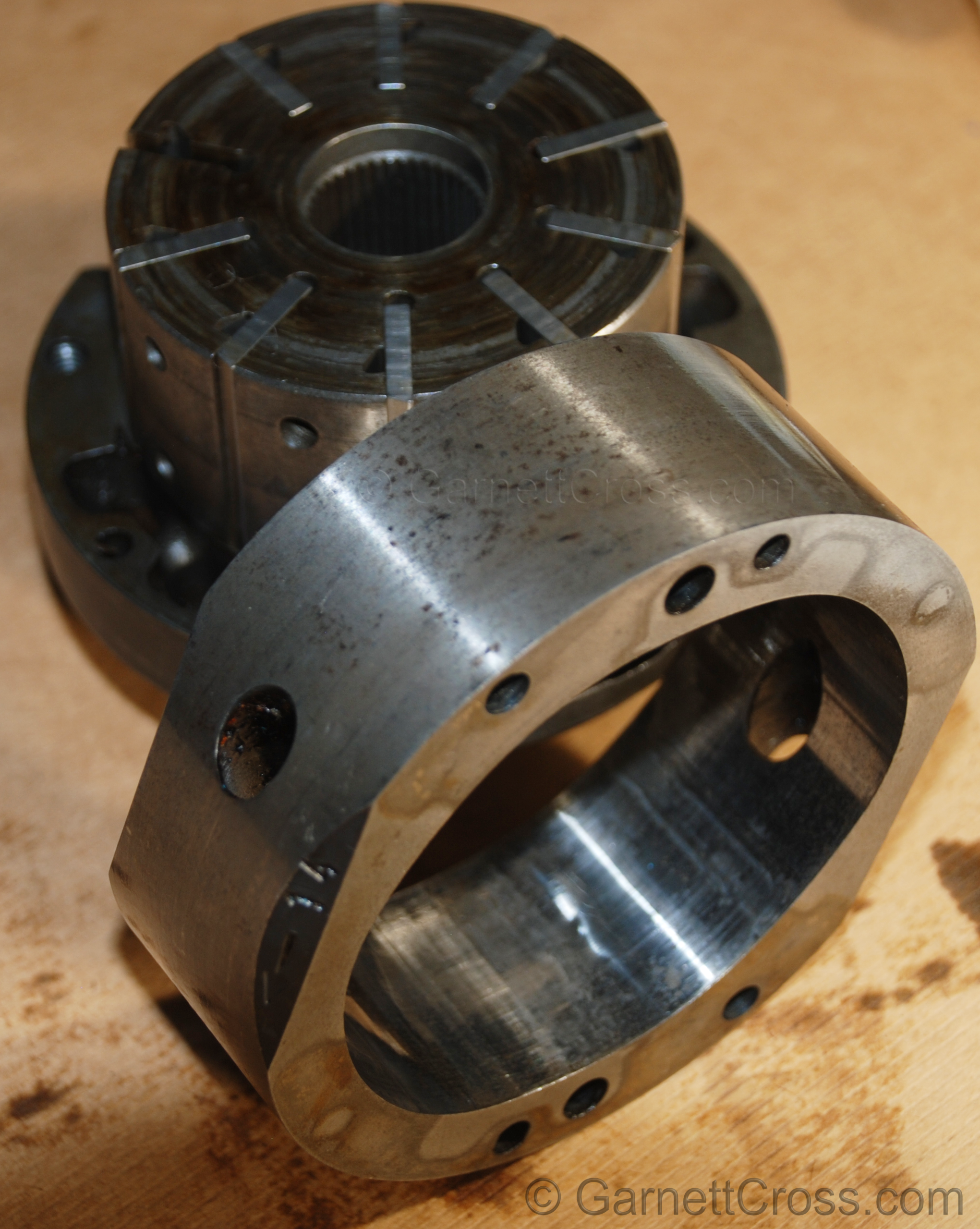
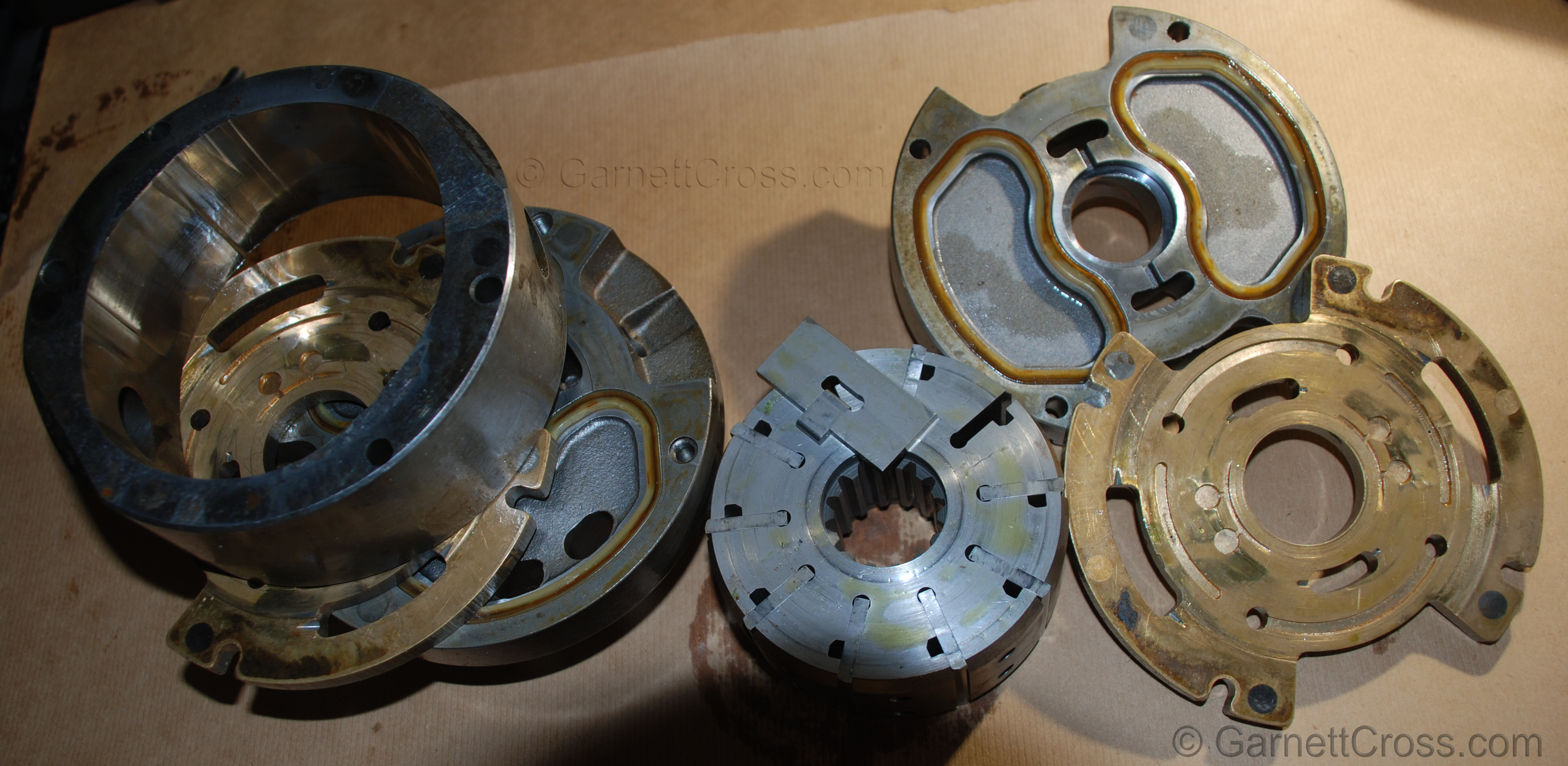
Oil Hydraulics Vane Pump Cartridge disassembled. | |
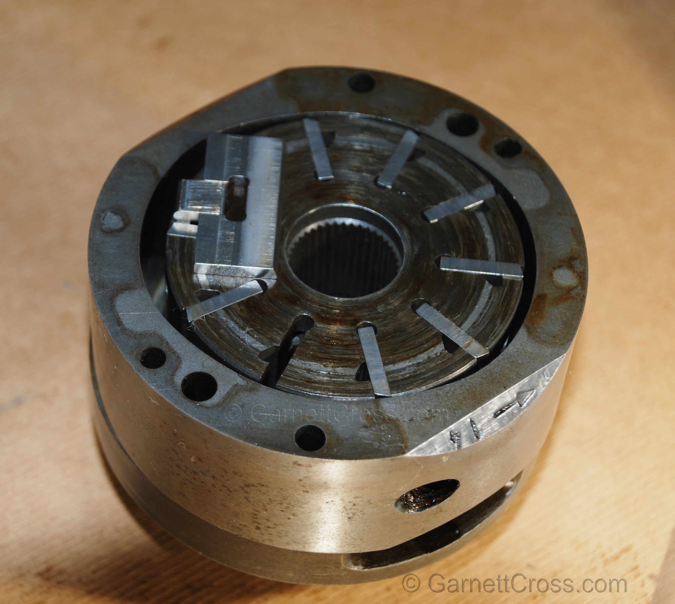
Oil Hydraulics Vane Pump Cartridge partially assembled Note: The arrow of rotation for the pump on the cam ring, the vanes must have the leading sharp edge against the cam ring (not all installed correctly in this image). The cartridge must be installed for the rotor to turn in the direction of the of the arrow on the cam ring. The number 14 on the cam ring is 14 US gallons(3.785 litres per US gallon) of oil per minute at 1200 RPM. | |
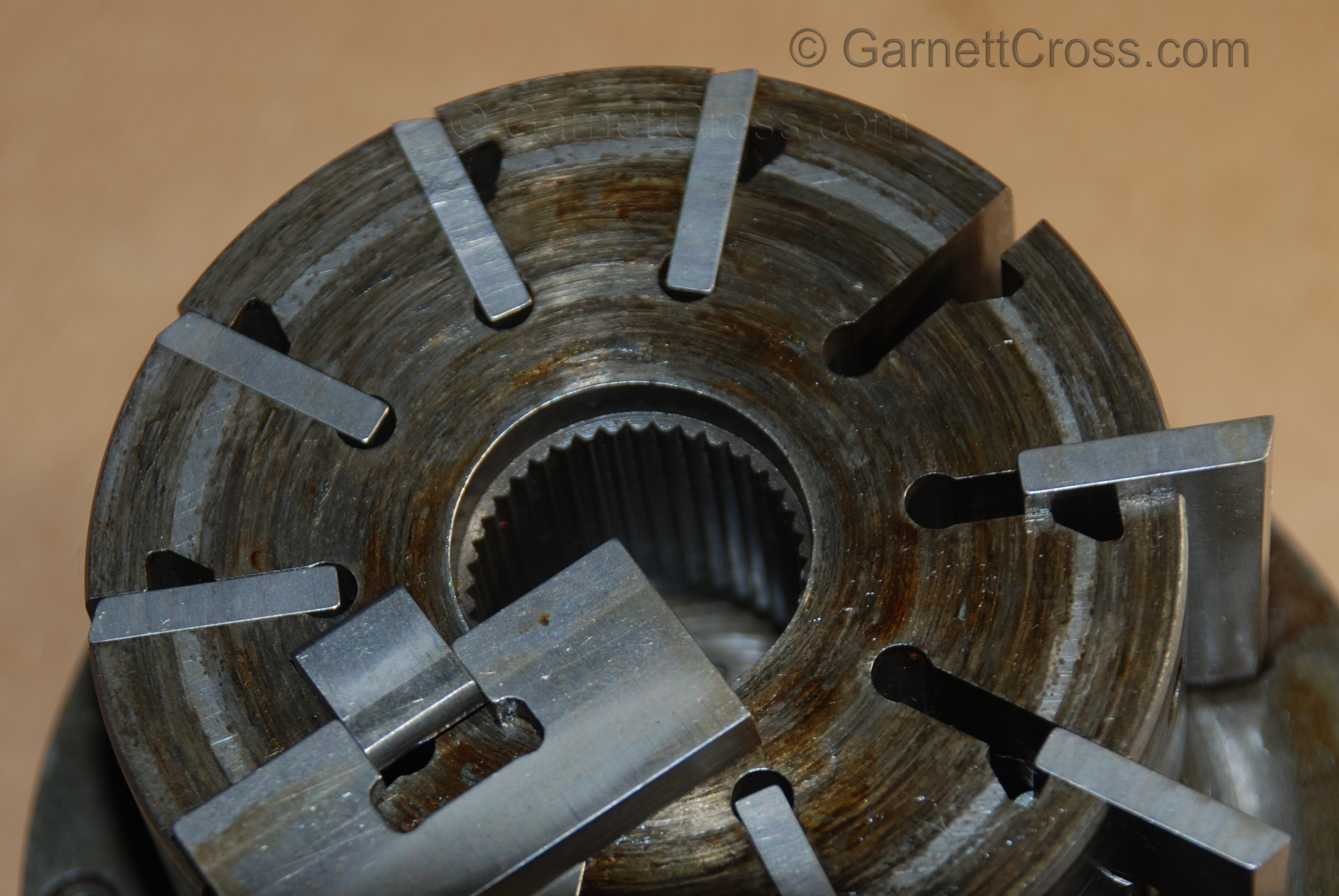
Oil Hydraulics Vane Pump Rotor,Vanes and Vane Insert (Intra-vane) visible Note: Not all the vanes are not installed in the same direction in this image. | |